-SCS Parameter Analyzer Reference Manual Appendix B: Using a Model 590 C-
4200A-901-01 Rev. C / February 2017 B-19
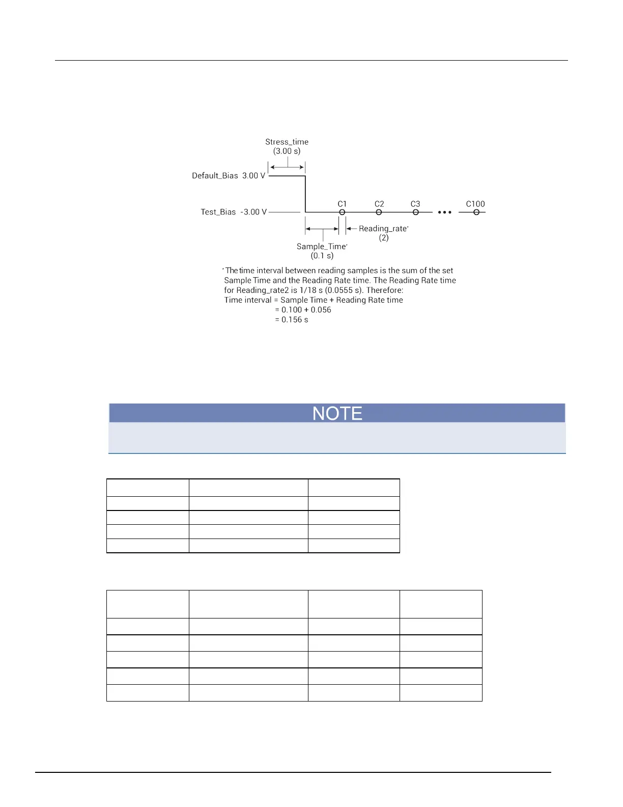
In this example, the 590 is set to source −5 V and performs 100 capacitance measurements using a
5 ms time interval, as shown in the following figure.
Figure 563: C-t measurements
If the file defined for CabCompFile does not exist, or there is no path specified (null string), the
default compensation parameters are used. When entering the path, use two backslash (\\)
characters to separate each directory. For example, if your cable file is in
C:\calfiles\590cal.dat, you enter the following:
C:\\calfiles\\590cal.dat
If a switch matrix to route signals is being controlled by a connection action (for example, connect),
there is no need to connect InputPin and OutPin. Set these parameters to 0.
For Range, the measurement range values are shown in the following table.
Range 100 kHz 1 MHz
The reading rates and resolutions for the ReadingRate parameter are described in the following
table.
Reading rate Nominal reading rate
(per second)
Display readings Resolution
(digits)
3 10 C,G,V 4.5
 Loading...


