MIPS R4000 Microprocessor User's Manual 403
R4000 Processor Interrupts
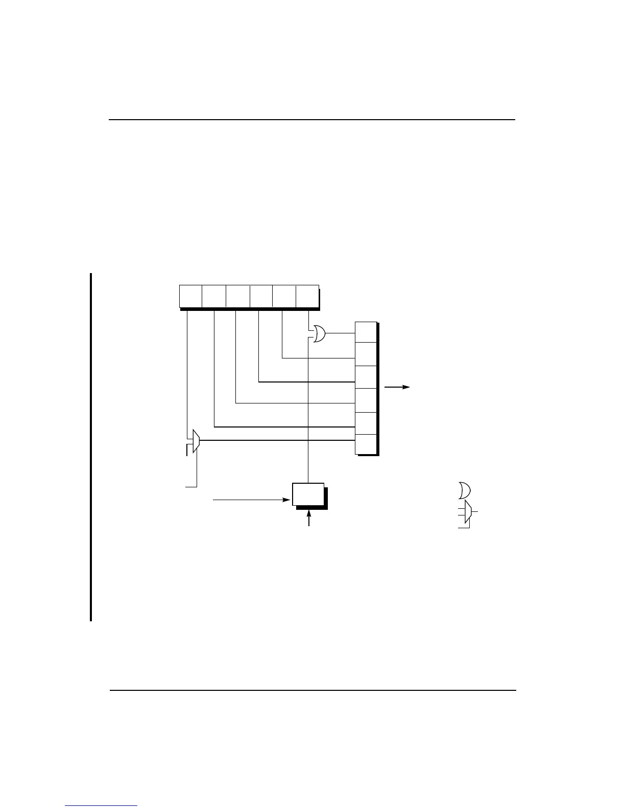
Figure 15-2 shows how the R4000SC and R4000MC interrupts are readable
through the Cause register.
• Bit 5 of the Interrupt register in the R4000SC and R4000MC is
multiplexed with the TimerInterrupt signal and the result is
directly readable as bit 15 of the Cause register.
• Bits 4:1 of the Interrupt register are directly readable as bits
14:11 of the Cause register.
• Bit 0 of the Interrupt register is latched into the internal register
by the rising edge of SClock, then ORed with the Int*(0) pin,
and the result is directly readable as bit 10 of the Cause register.
Figure 15-2 R4000SC/MC Interrupt Signals
The select line for the Timer Interrupt multiplexer is enabled by boot-
mode bit 19, TimerIntDis, as described in Chapter 9. The Timer Interrupt
input to the multiplexer is asserted when the Count register equals the
Compare register.
21
0
4
3
Cause
register(15:10)
5
IP4
IP3
IP2
IP6
IP5
IP7
Interrupt register (5:0)
Timer
Interrupt
multiplexer
OR gate
12 11
10
14 1315
See Figure 15-5.
SClock
(Internal
register)
Int*(0)
TimerIntDis