Chapter 15
404 MIPS R4000 Microprocessor User's Manual
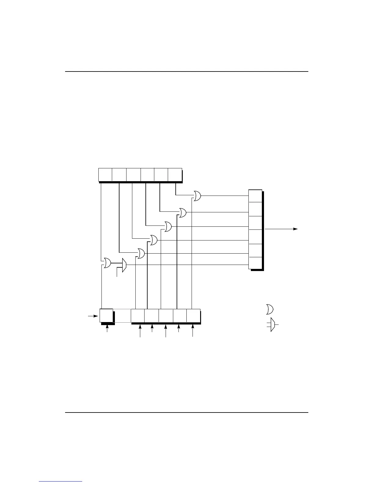
Figure 15-3 shows how the R4000PC interrupts are readable through the
Cause register. The interrupt bits, Int*(5:0), are latched into the internal
register by the rising edge of SClock.
• Bit 5 of the Interrupt register in the R4000PC is ORed with the
Int*(5) pin and then multiplexed with the TimerInterrupt
signal. This result is directly readable as bit 15 of the Cause
register.
• Bits 4:0 of the Interrupt register are bit-wise ORed with the
current value of the interrupt pins Int*[4:0] and the result is
directly readable as bits 14:10 of the Cause register.
Figure 15-3 R4000PC Interrupt Signals
Cause
register
Interrupt register (5:0)
Int*(5)
Timer
Interrupt
multiplexer
OR gate
Int*(4)
21
0
4
35
10
3
24
See
Figure 15-5.
5
SClock
(Internal
register)
Int*(0)
Int*(3)
Int*(2)
Int*(1)
IP4
IP3
IP2
IP6
IP5
IP7
12 11
10
14 1315