MIPS R4000 Microprocessor User's Manual E-3
PLL Passive Components
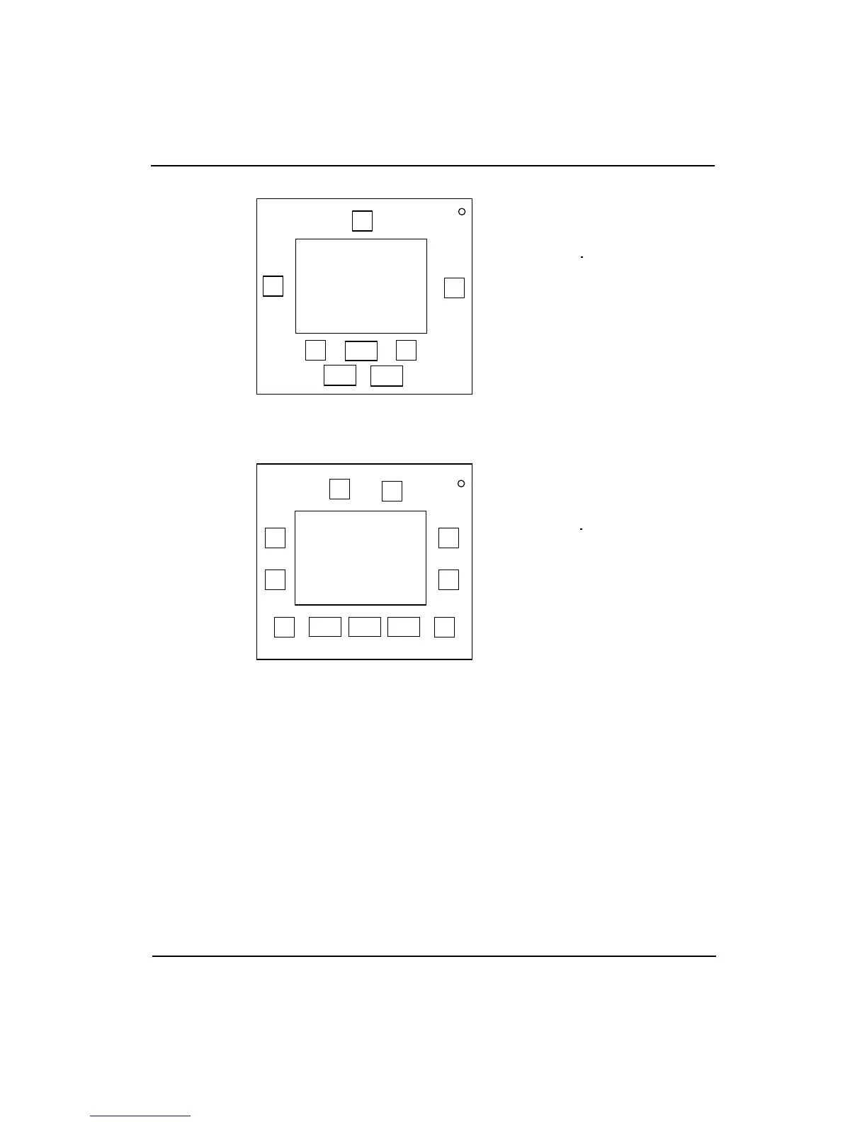
Figure E-2 shows a top view of the 179-pin package with capacitors.
Figure E-2 179-Pin Package
Figure E-3 shows a top view of the 447-pin package with chip capacitors.
Figure E-3 447-Pin Package
It is essential to isolate the analog power and ground for the PLL circuit
(VccP/VssP) from the regular power and ground (Vcc/Vss). Initial
evaluations have yielded good results with the following values:
R = 5 ohms C1 = 1 nF C2 = 82 nF
C3 = 10 µF Cp = 470 pF
Since the optimum values for the filter components depend upon the
application and the system noise environment, these values should be
considered as starting points for further experimentation within your
specific application. In addition, the chokes (inductors: L) can be
considered for use as an alternative to the resistors (R) for use in filtering
the power supply.
%1
C2
%2
x: Vss-Vcc Bypass Caps
x
x
x
x
x
die
C2: VssP-VccP Bypass Caps
%1, %2: PLL Caps
%1 C2 %2
x: Vss-Vcc Bypass Caps
x
x x
die
C2: VssP-VccP Bypass Caps
%1, %2: PLL Caps
x
x
x
x
x