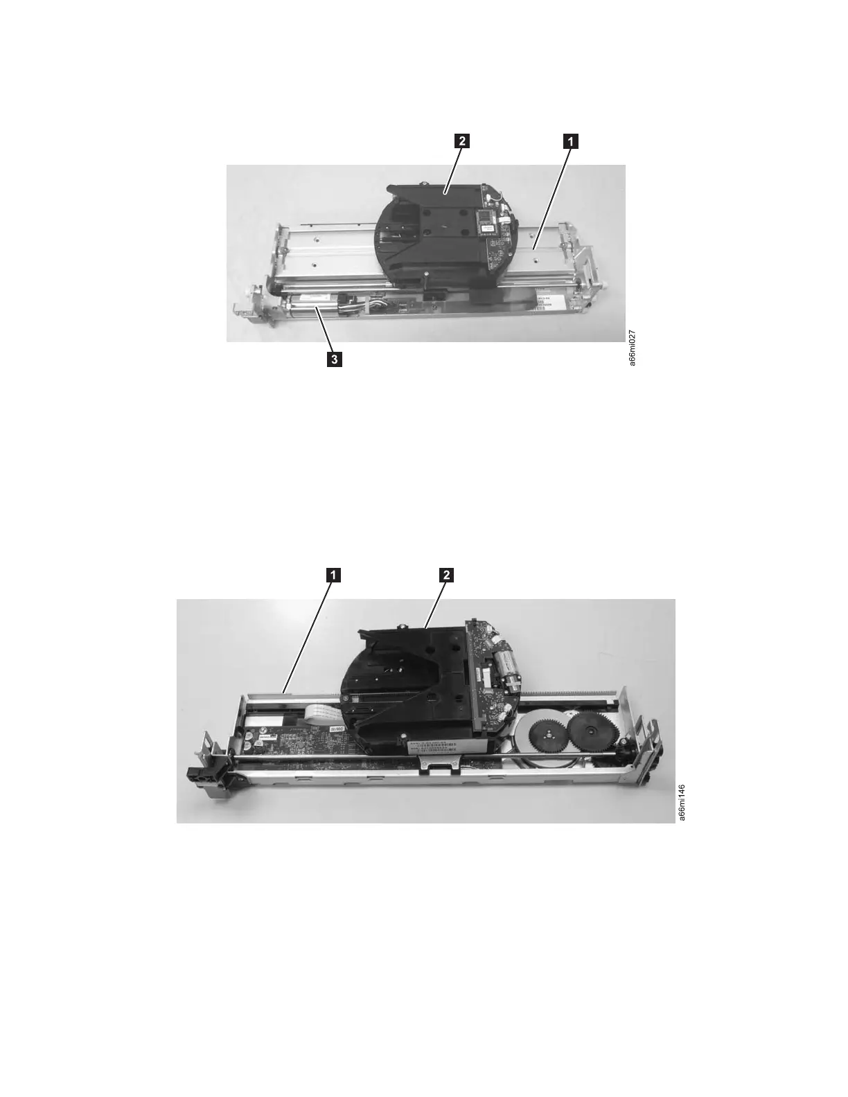
Y-Axis/Picker Assembly
The Y-Axis/Picker Assembly houses the Y Motor 3 and the Picker Assembly 2,
which is attached to the Carrier 1. The Carrier moves the Y-Axis/Picker
Assembly within the library.
M2 Robot Assembly
While serving the same function as that of the Robot Assembly, the M2 Robot
Assembly has a different design style which is depicted in the following images.
In the M2 Robot Assembly, the Robot Assembly houses the Y-Axis controller board
(1) and the M2 Picker Assembly (2 ) is attached to the Carrier.
The M2 label is clearly visible on the side of the Robot Assembly which faces the
door of the library. See Figure 2-7 on page 2-10.
Figure 2-5. Y-Axis/Picker Assembly
Figure 2-6. M2 Robot Assembly
Chapter 2. Product Description 2-9