-SCS Parameter Analyzer Reference Manual Appendix L: Wafer-
level reliability testing
4200A-901-01 Rev. C / February 2017 L-17
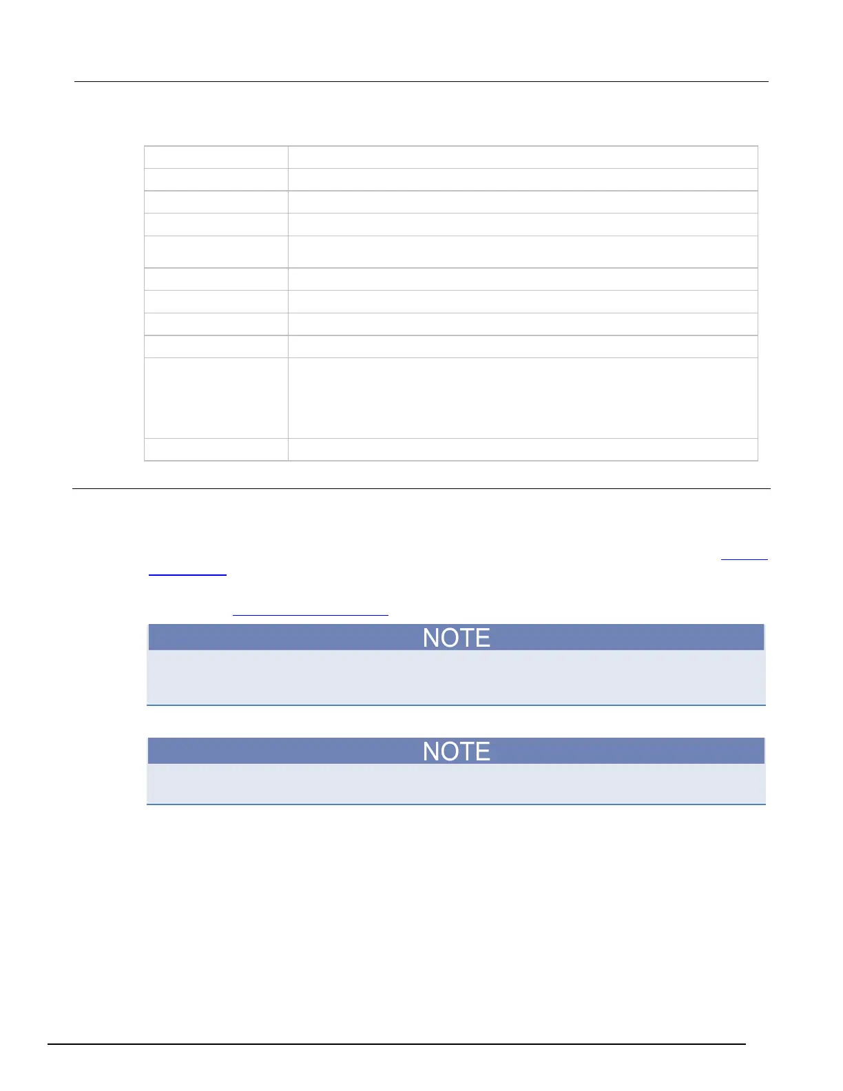
Output variables
Time stamp array indicating when current is measured
Charge-to-breakdown; cumulative charge (C) passing through the oxide before
breakdown (Ref. JESD35-A)
Charge-to-breakdown density (C/cm
) (Ref. JESD35-A)
Applied voltage at the step just before oxide breakdown (Ref. JESD35-A)
Measured current at v_bd, just before oxide breakdown
Time stamp when measuring I_bd
•
• Catastrophic failure (initial test pass, ramp test fail, post test fail)
• Masked Catastrophic (initial test pass, ramp test pass, post test fail)
• Non-Catastrophic (initial test pass, ramp test fail, post test pass)
•
Others (initial test pass, ramp test pass, post test pass)
Details
Performs a Charge-to-Breakdown test using the QBD J-ramp test algorithm described in JESD35-A
"Procedure for Wafer-Level Testing of Thin Dielectrics," April 2011. This algorithm forces a
logarithmic current ramp until the oxide layer breaks down. This algorithm is capable of a maximum
current of ±1 A if a high power SMU is used. The flow diagram for the V-ramp test is shown in
J-ramp
flow diagram (on page L-19).
See JEDEC standard JESD35-A "Procedure for Wafer-Level Testing of Thin Dielectrics," April 2011,
referenced in Signatone CM500 Prober (on page K-1
).
Some of the descriptions of the following input variables and output variables are quoted from the
JESD35-A standard. The variables quoted from the standard include this reference identification:
(Ref. JESD35-A).
Notes on input variables
If there is no switching matrix in the system, input either 0 or -1 for hi_pin and lo_pins to bypass
switch.
I_init: For maximum sensitivity, the specified value should be well above the worst-case oxide
current of a "good" oxide and well above the system noise floor. Higher values must be specified for
ultra-thin oxide because of direct tunneling effects (Ref. JESD35-A).
 Loading...


