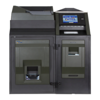
5-29
5
Door open Solenoid is unable to unlock the door.
1) Check the Distribution PCB data cable connection on the Control Computer
2) Check the Solenoid plunger for ease of movement.
3) Use the Diagnostic Menu to activate the Solenoid and check voltage to the Solenoid.
Login > Maintenance Menu > Door Solenoids and Sensors
X Activate the Solenoid by tapping the displayed door area.
If the Solenoid does not activate:
a) Check voltage at the “quick connect” on the Solenoid cable - when activated, the
voltmeter will display 14 ~ 24 VDC, then drop to approximately +3 VDC ~ +5 VDC (in-
dicates normal functionality).
If so, the Solenoid Plunger may be binding or the Solenoid may be defective
b) If not:
Check the Solenoid connection at terminal J30 on the Distribution PCB
c) Insure +24 VDC is present at terminal J20 on the Distribution PCB.
If so, possible defective Distribution PCB
Incorrect Solenoid activates when a Vault is selected:
1) Verify the Solenoid cable is connected to the correct terminal on the Distribution PCB.
Note Recycler Vault is unsecure - Please Secure the Note Recycler Door
1) Insure the Note Recycler Door is shut and the Handle is in the locked position.
2) Insure the Combination Lock is in the locked position.
3) Perform a power reset, (place the ON/OFF switch in the OFF position for 30 seconds minimum).
4) Insure the Solenoid Plunger moves freely.
5) Log into the Door Diagnostic menu and block/unblock the sensors to check operation.
Log In > More > Maintenance > Diagnostics > Doors
6) Check the connection at the Vault Door Locking Bolt Position Sensor.
7) Check the connection at Solenoid Plunger position Sensor.
8) Check the connections at terminal J42 and J43 on the Distribution PCB.
9) Replace the suspected defective Sensor.
10) Replace the Distribution PCB.
Solenoids and Sensors