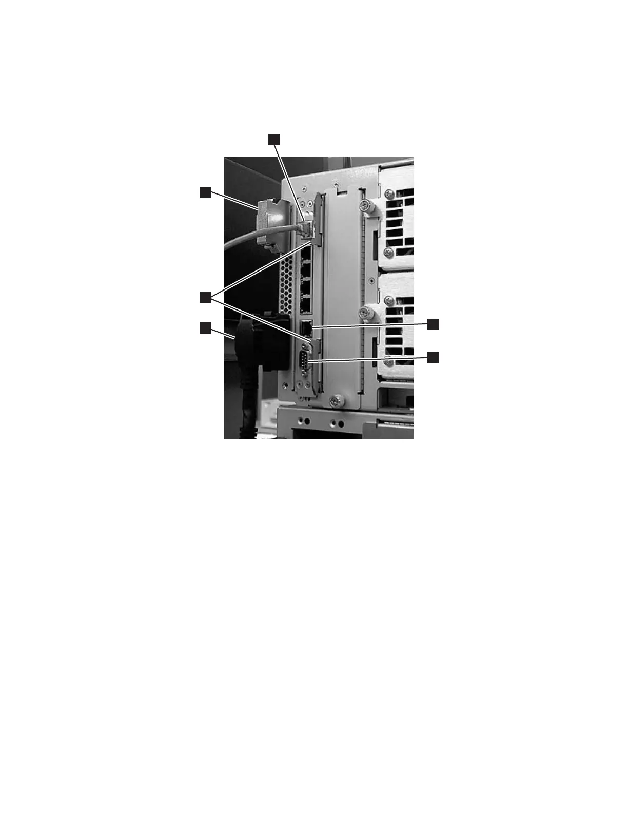
Note: Six slots reside below the Ethernet cable. The four topmost slots are
reserved for future use. The two bottommost slots are designated as
Ethernet (5 in Figure 8-49) and serial (6 in Figure 8-49) ports, and are
reserved for use by IBM Service Personnel.
1 Module communication
terminator
4
Module-to-module communication cable
2 Ethernet cable (customer
supplied)
5
Ethernet port (for IBM service personnel use)
3 Latches 6 Serial port (for IBM service personnel use)
3. Grasp the pair of latches (3 in Figure 8-49) near the top and bottom of the
LCB. Simultaneously push the latches to the left, and then pull them out and
away from the LCB.
4. Simultaneously grasp the same pair of latches again, and slowly pull them
toward you. As the LCB begins to slide out of the control module, be sure to
support the LCB from underneath, being careful to touch only the metal cover
and the ground plane.
Important: DO NOT touch any components on the LCB firmware board.
Hold it by the metal cover and support it by the metal ground
plane along the bottom edge.
5. Once the LCB has been removed from the control module, carefully lay it
(Figure 8-50 on page 8-48) on a clean, flat surface.
1
2
4
5
6
a66ug014
3
Figure 8-49. Library Control Blade (LCB)
Chapter 8. Add, Check, Adjust, Remove, and Replace Procedures 8-47