This rotates the threader motor worm gear (6 in Figure 8-136 on page 8-126)
clockwise, drawing the tape leader block assembly (LBA) into the cartridge.
4. As the LBA is secured in the cartridge, you should hear the LBA retention
spring clips click into place. If you do not hear the click, continue rolling until
the threader motor worm gear (4 in Figure 8-136 on page 8-126) stops. The
LBA is in the correct position.
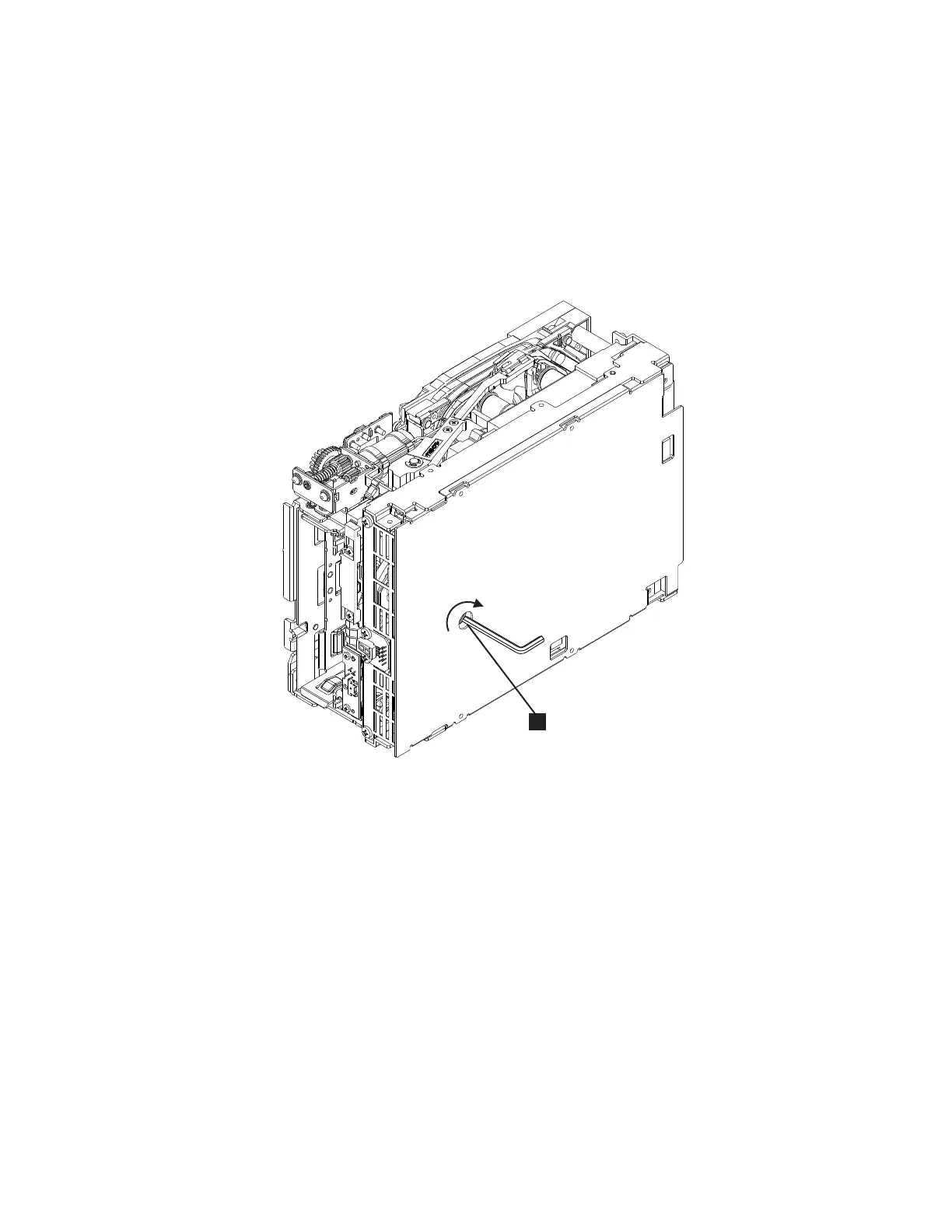
Note: Be sure to keep tension on the tape as the LBA is drawn into the
cartridge by using a hex wrench (1) in Figure 8-137.
5. Notice the following:
a. Loader mechanism gear (8 in Figure 8-136 on page 8-126) nearest the
front of the drive that actuates the cartridge loader mechanism
b. Position of the rotator stub (3 in Figure 8-136 on page 8-126).
c. Front loader motor worm gear (8 in Figure 8-136 on page 8-126).
Rotating this gear allows the loader mechanism gear (1 in Figure 8-136
on page 8-126) to turn.
6. Rotate the loader motor worm gear (1 in Figure 8-136 on page 8-126) to turn
the loader mechanism gear (6 in Figure 8-136 on page 8-126)
counterclockwise. Continue turning until the rotator stub (3 in Figure 8-136
on page 8-126) loses contact with the lever (7 in Figure 8-136 on page 8-126).
This releases the LBA leader pin.
7. Rotate the threader motor worm gear (4 in Figure 8-136 on page 8-126) to
turn the threader mechanism gear (6 in Figure 8-136 on page 8-126)
counterclockwise. This moves the LBA out of the cartridge and past the
read/write head. Stop this rotation when the LBA is near the tape guide roller
a82ru008
1
Figure 8-137. Using hex wrench to rewind tape into cartridge
Chapter 8. Add, Check, Adjust, Remove, and Replace Procedures 8-127