9. Rotate the threader motor worm gear (4 in Figure 8-144 on page 8-134) to
turn the threader mechanism gear (6 in Figure 8-144 on page 8-134)
counterclockwise. This moves the LBA out of the cartridge and past the
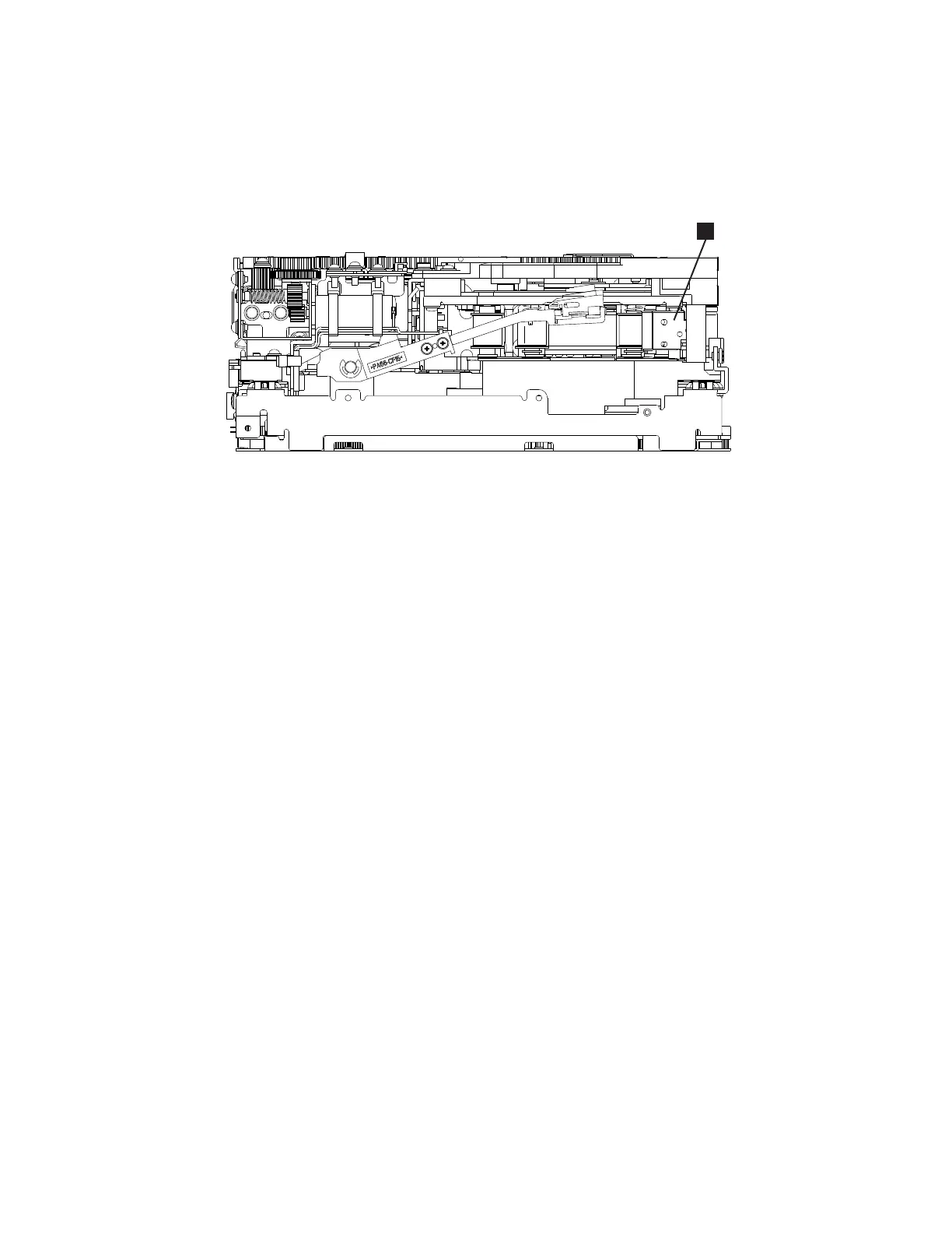
read/write head. Stop this rotation when the LBA is near the tape guide roller
nearest the rear of the drive shown as 1 Figure 8-145.
10. Continue rotating the loader motor worm gear (1 in Figure 8-144 on page
8-134) until the rotator stub (3 in Figure 8-144 on page 8-134) is positioned
as shown. Notice that the rotator stub (3 in Figure 8-144 on page 8-134) is
nearly aligned with the cartridge loader tray guide bearing (2 in
Figure 8-144 on page 8-134).
11. Remove the cartridge from the cartridge loader tray.
12. Reassemble the drive by reversing the procedure in Step 5 in “Beginning
Procedure” on page 8-123.
13. Refer to the appropriate procedure to install the new drive and return the
failed drive.
a82ru010
1
Figure 8-145. Leader Block Assembly (LBA)
Chapter 8. Add, Check, Adjust, Remove, and Replace Procedures 8-135