EasyManuals Logo

IBM TS3310 User Manual

IBM TS3310
531 pages
To Next Page IconTo Next Page
To Previous Page IconTo Previous Page
Page #304 background imageLoading...
Page #304 background image
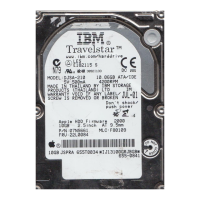
4. Remove the large black connector. See Figure 8-62.
a. Pinch the latch (1 in Figure 8-62) on the cable connector.
b. Carefully lift up on the connector.
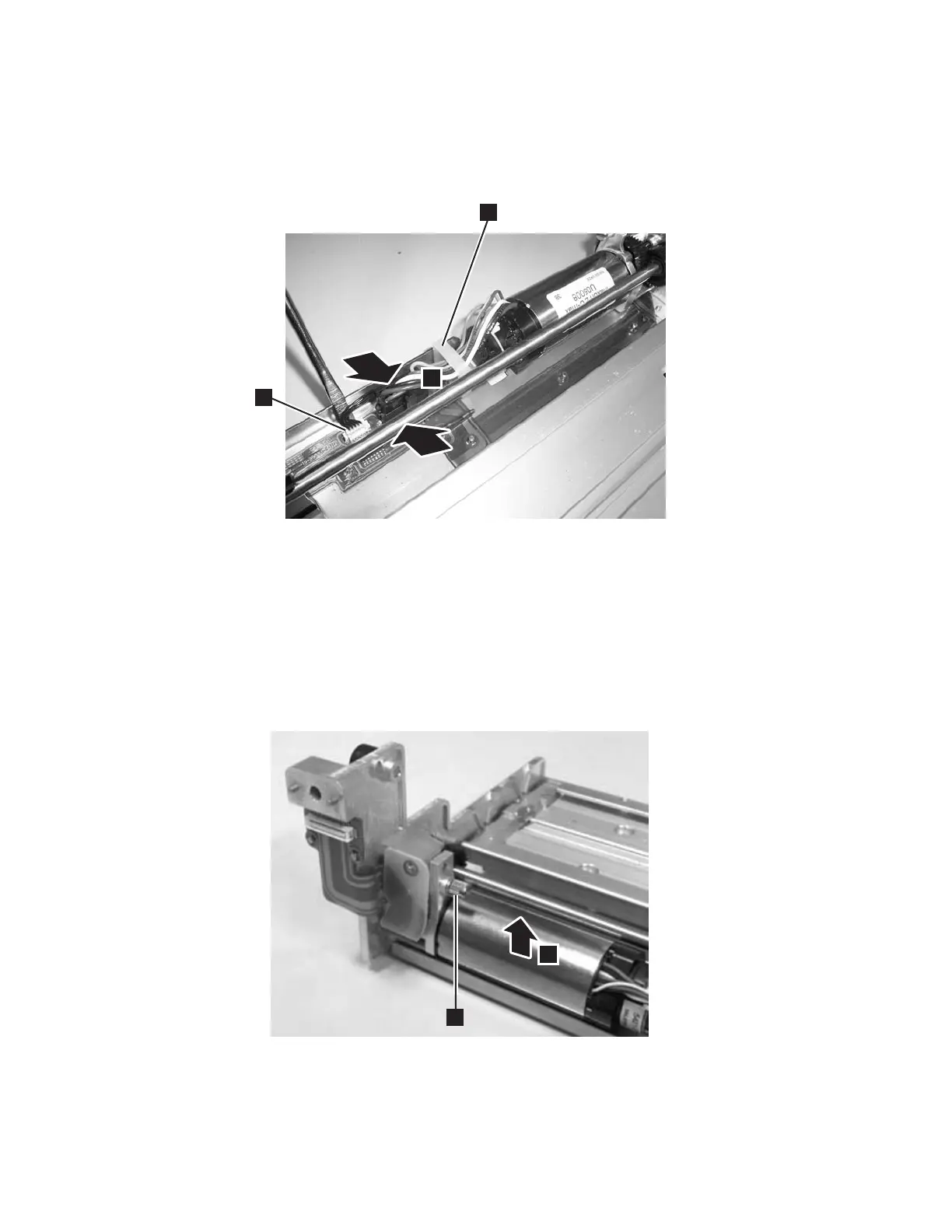
5. Use a small flat blade screw driver to pry up on the small white connector (2
in Figure 8-63) gently working the screw driver blade along the entire outside
edge of the connector.
Important: Be very careful not to damage the connector.
6. Loosen the thumb screw (1 in Figure 8-63), slide the motor to the left, then
lift the motor out of the Robot Assembly (2 in Figure 8-63).
a66mi004
1
2
3
Figure 8-62. Y motor connector
a66mi005
1
2
Figure 8-63. Y motor thumb screw
8-62 TS3310 Tape Library Maintenance Information

Table of Contents

Questions and Answers:

Question and Answer IconNeed help?

Do you have a question about the IBM TS3310 and is the answer not in the manual?

IBM TS3310 Specifications

General IconGeneral
Form FactorRack-mountable
Tape TechnologyLTO Ultrium
Product TypeTape Library
InterfaceFibre Channel
ExpansionExpandable with additional modules
Supported Tape TechnologyLTO Ultrium 5, LTO Ultrium 6
Weight120 lb (54.4 kg) (fully configured)
Power SupplyDual redundant power supplies
Operating Temperature41°F to 95°F (5°C to 35°C)
Non-operating Temperature-40°F to 140°F (-40°C to 60°C)
Humidity20% to 80% non-condensing

Related product manuals