Replacing the Y Motor in the Y-axis/Picker Assembly in a
Stand-alone Library
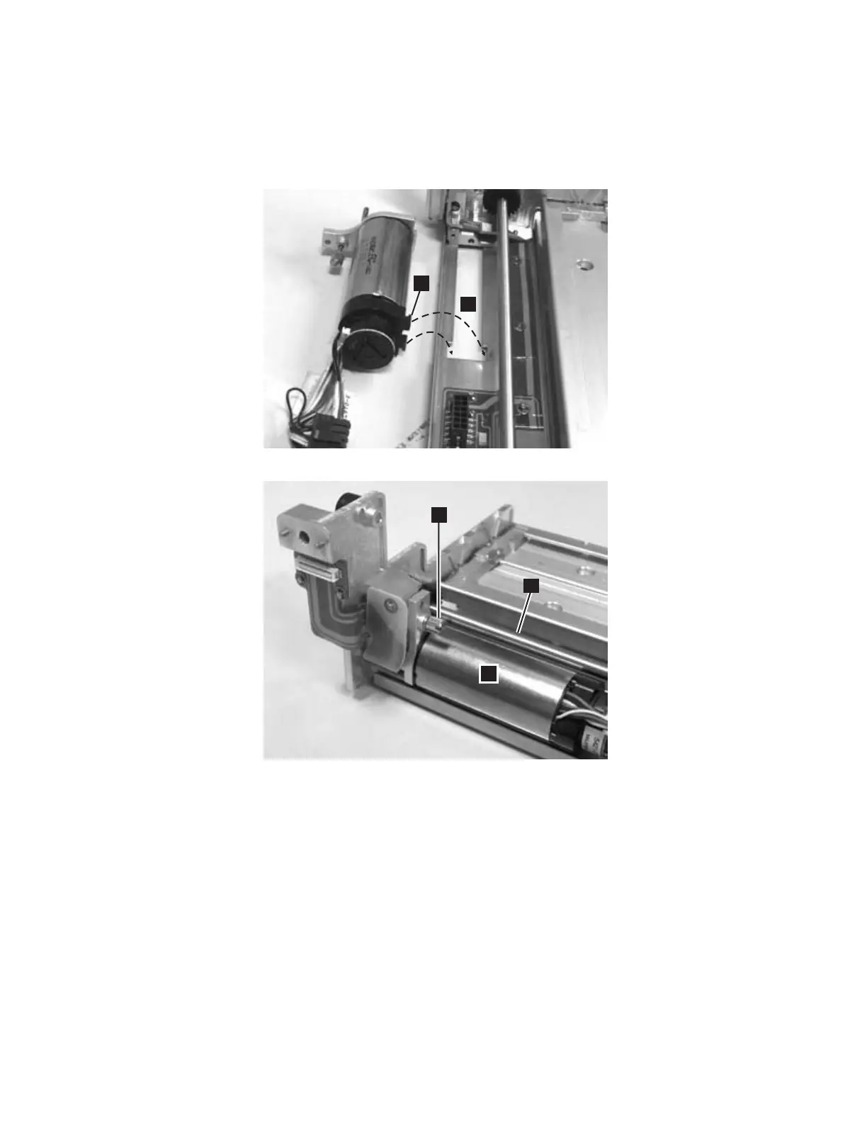
1. Ensure that the black plastic piece on the wiring end of the motor (1 in
Figure 8-64) fits into the slot in the base plate (2 in Figure 8-64).
Note: The top of the motor (4 in Figure 8-64) must be parallel with the Picker
guide rod (5 in Figure 8-64).
2. Install the Y Motor in the Y-axis/Picker Assembly and tighten the thumb screw.
The small gear on the Y Motor must connect with the larger gear on the
Y-axis/Picker Assembly.
3. Connect the small white connector (2 in Figure 8-65 on page 8-64).
Important: Be very careful not to damage the connector.
4. Connect the large black connector. See Figure 8-65 on page 8-64.
a66mi006
1
2
3
4
5
Figure 8-64. Correct Y motor position
Chapter 8. Add, Check, Adjust, Remove, and Replace Procedures 8-63