(7) Install the strut assembly to steering knuckle
attaching bolts. Install nuts on attaching bolts (Fig.
17). Tighten the strut assembly to steering knuckle
bolt nuts to 169 N·m (125 ft. lbs.). TURN NUTS ON
BOLTS. DO NOT TURN BOLTS.
CAUTION: The hub and bearing assembly to stub
shaft retaining nut is a prevailing torque nut and
can not be re-used. A NEW retaining nut MUST be
used when assembled.
(8) Install a NEW retaining nut (Fig. 18).
Tighten, but do not torque the hub nut at this
time.
(9) Install speed sensor cable routing bracket on
front strut assembly. Install and securely tighten
routing bracket screw.
(10) Install the braking disk on the hub and bear-
ing assembly (Fig. 19).
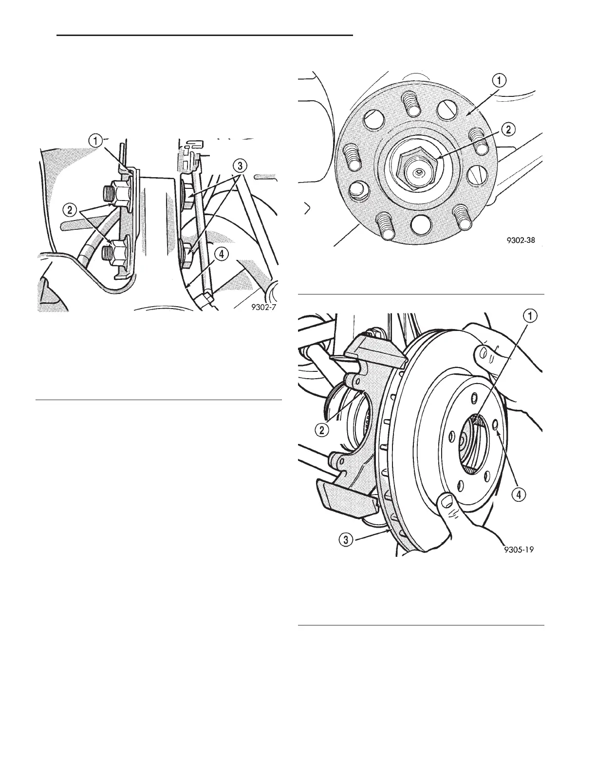
Fig. 17 Strut Assembly to Steering Knuckle
Attaching Bolts
1 – STRUT ASSEMBLY
2 – NUTS
3 – STRUT ASSEMBLY TO STEERING KNUCKLE ATTACHING
BOLTS
4 – STEERING KNUCKLE
Fig. 18 Hub And Bearing To Stub Axle Retaining Nut
1 – HUB/BEARING ASSEMBLY
2 – NUT
Fig. 19 Installing Braking Disc
1 – HUB
2 – STEERING KNUCKLE
3 – BRAKING DISC (ROTOR)
4 – WHEEL MOUNTING STUD
LH DIFFERENTIAL AND DRIVELINE 3 - 9
REMOVAL AND INSTALLATION (Continued)