PROPORTIONING VALVE APPLICATIONS AND PRESSURE SPECIFICATIONS
Sales
Code
Brake System Type Split Point Slope Identification
Inlet
Pressure
Outlet
Pressure
All All Disc/Disc 350 psi 0.34 Bar Code Label 1000 psi 525-625 psi
BRAKE ROTOR
Any servicing of the rotor requires extreme care to
maintain the rotor within service tolerances to
ensure proper brake action.
Excessive runout or wobble in a rotor can increase
pedal travel due to piston knock-back. This increases
guide pin sleeve wear due to the tendency of the cal-
iper to follow the rotor wobble.
When diagnosing a brake noise or pulsation, the
machined disc braking surface should be checked and
inspected.
BRAKING SURFACE INSPECTION
Light braking surface scoring and wear is accept-
able. If heavy scoring or warping is evident, the rotor
must be refaced or replaced. Refer to SERVICE PRO-
CEDURES in this section of this group for informa-
tion on brake rotor machining.
Excessive wear and scoring of the rotor can cause
improper lining contact on the rotor’s braking sur-
face. If the ridges on the rotor are not removed before
new brake shoes are installed, improper wear of the
shoes will result.
If a vehicle has not been driven for a period of
time, the rotor’s braking surface will rust in the
areas not covered by the brake shoes at that time.
Once the vehicle is driven, noise and chatter from
the disc brakes can result when the brakes are
applied.
Some discoloration or wear of the rotor surface is
normal and does not require resurfacing when lin-
ings are replaced. If cracks or burned spots are evi-
dent, the rotor must be replaced.
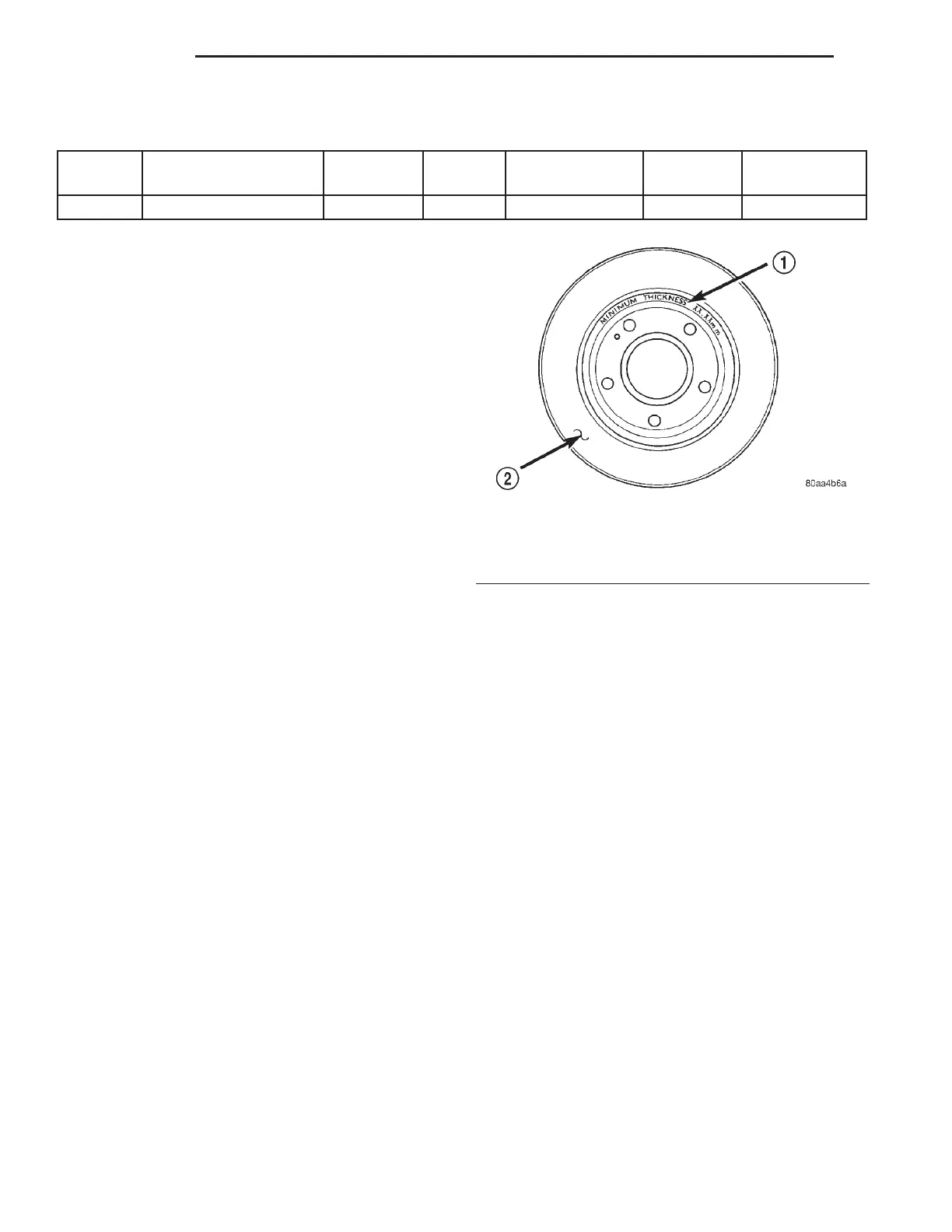
ROTOR MINIMUM THICKNESS
Measure rotor thickness at the center of the brake
shoe contact surface. Replace the rotor if it is worn
below minimum thickness or if machining the rotor
will cause its thickness to fall below specifications.
CAUTION: Do not machine the rotor if it will cause
the rotor to fall below minimum thickness.
Minimum thickness specifications are cast on the
rotor’s unmachined surface (Fig. 18). Limits can also
be found in the table at the end of this brake rotor
information.
ROTOR THICKNESS VARIATION
Thickness variation in a rotor’s braking surface
can result in pedal pulsation, chatter and surge. This
can also be caused by excessive runout in the rotor or
the hub.
Rotor thickness variation measurements should be
made in conjunction with measuring runout. Mea-
sure thickness of the brake rotor at 12 equal points
around the rotor braking surface with a micrometer
at a radius approximately 25 mm (1 inch) from edge
of rotor (Fig. 19). If thickness measurements vary by
more than 0.013 mm (0.0005 inch), the rotor should
refaced or replaced. Refer to SERVICE PROCE-
DURES in this section of this group for information
on brake rotor machining.
ROTOR RUNOUT
On-vehicle rotor runout is the combination of the
individual runout of the hub face and the runout of
the rotor. (The hub and rotor runouts are separable).
To measure rotor runout on the vehicle, first remove
the tire and wheel assembly. Reinstall the wheel
mounting nuts on the studs, tightening the rotor to
the hub. Mount the Dial Indicator, Special Tool
C-3339, with Mounting Adaptor, Special Tool SP-
1910 on steering arm. The dial indicator plunger
should contact braking surface of rotor approximately
25 mm (one inch) from outer edge of rotor (Fig. 20).
Fig. 18 Minimum Brake Rotor Thickness Markings
(Typical)
1 – ROTOR MINIMUM THICKNESS MARKING
2 – ROTOR
5 - 16 BRAKES LH
DIAGNOSIS AND TESTING (Continued)