listed below. Be sure to place the tubing nut on
tube before proceeding to flare the tubing.
(1) Carefully prepare the end of the tubing to be
flared. Be sure the end of the tubing is square and
all burrs on the inside of the tubing are removed
(Fig. 33). This preparation is essential to obtain
the correct form of a (metric) ISO tubing flare.
(2) Open the jaws of the Flaring Tool. Align the
jaws of the flaring tool around the tubing. Close the
jaws of the Flaring Tool around the tubing, but do
not lock the tubing in place.
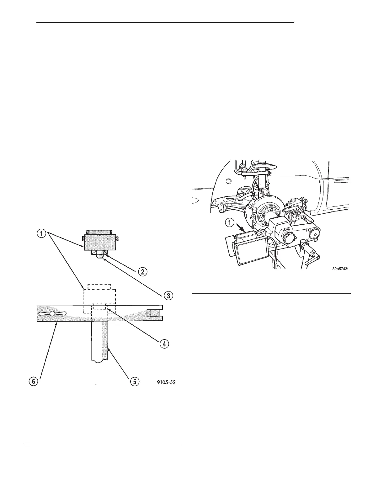
(3) Position tubing in jaws of the Flaring Tool so
that it is flush with top surface of flaring tool bar
assembly (Fig. 34).
(4) Install the correct size adaptor for the brake
tubing being flared, on the feed screw of the yoke
assembly. Center the yoke and adapter over the end
of the tubing. Apply lubricant to the adapter area
that contacts the brake tubing. Make sure the
adapter pilot is fully inserted in the end of the brake
tubing. Tighten screw on yoke assembly until the
adaptor has seated squarely on the surface of the bar
assembly (Fig. 34). This process will properly create
a metric ISO tubing flare.
BRAKE ROTOR MACHINING
BRAKE ROTOR MACHINING
NOTE: Refacing of the rotor is not required each
time the brake pads are replaced.
Any servicing of the rotor requires extreme care to
maintain the rotor within service tolerances to
ensure proper brake action.
If the rotor surface is deeply scored or warped, or
there is a complaint of brake roughness or brake
pedal pulsation, the rotor should be refaced using a
hub-mounted on-car brake lathe (Fig. 35), or
replaced.
The use of a hub-mounted on-car brake lathe is
highly recommended to eliminate the possibility of
excessive runout. It trues the brake rotor to the vehi-
cle’s hub and bearing.
NOTE: All rotors have markings for minimum allow-
able thickness cast on an un-machined surface of
the rotor (Fig. 36) or (Fig. 37).
Minimum allowable thickness is the minimum
thickness which the brake rotor machined surface
may be cut to.
CAUTION: Do not machine the rotor if it will cause
the rotor to fall below minimum thickness.
Before installation, verify the brake rotor face and
the hub adapters are free of any chips, rust, or con-
tamination.
Fig. 34 ISO Tubing Flare Tool
1 – ADAPTER
2 – LUBRICATE HERE
3 – PILOT
4 – FLUSH WITH BAR
5 – TUBING
6 – BAR ASSEMBLY
Fig. 35 Refacing Brake Rotor
1 – ON-CAR BRAKE LATHE
LH BRAKES 5 - 23
SERVICE PROCEDURES (Continued)