• Seat Track Rearward
• Seat Front Down
• Seat Rear Down
• Seat Recliner Rearward
• Seat Track Forward
• Seat Front Up
• Seat Rear Up
• Seat Recliner Forward
DIAGNOSIS AND TESTING
DIAGNOSTIC PROCEDURE
Before any testing is attempted the battery should
be carefully charged and all connections and termi-
nals cleaned and tightened to insure proper continu-
ity and grounds.
With dome lamp on, apply switch in direction of
failure. If dome lamp dims the seat motor is trying to
work indicating mechanical jamming. If dome lamp
does not dim, then proceed with the following electri-
cal tests.
CIRCUIT BREAKER
Find correct circuit breaker on fuse block. Pull out
slightly but be sure that circuit breaker terminals
still contact terminals in fuse block. Connect ground
wire of voltmeter to a good ground. With probe of
voltmeter positive wire, check both terminals of cir-
cuit breaker for battery voltage. If only one terminal
checks at battery voltage, circuit breaker is defective
and must be replaced. If neither terminal shows bat-
tery voltage, check for open or shorted circuit to cir-
cuit breaker.
POWER SEAT SWITCH DIAGNOSTIC TEST
The Power Seat Switch Diagnostic Test can be
used to test whether the switch activations are being
recognized by the MHSMM.
ACTIVATION
The Power Seat Switch Diagnostic Test can only be
activated by sending the proper PCI bus command
via the DRB lll scan tool to enter diagnostic test
number 2.
Upon activation of the test the operator has ten
seconds to activate all switches, manual seat
switches - all 8 directions, 3 memory switches, and
both driver and passenger heat HI and LO requests,
but not including the mirrors.
At the conclusion on the ten-second period, the
MHSMM can be requested to provide both Pass/Fail
test information. A Pass condition occurs only if all
the switches are activated. If any of the switches are
not activated, Fail will be registered.
Should a Fail condition occur, the individual switch
information could be accessed using the proper com-
mands on the DRB lll scan tool.
MOTOR TESTS
(1) Remove power seat switch from seat. Refer to
Seat Switch Removal and Installation in this group.
(2) Disconnect wire harness connector.
(3) Check Pin 1 for battery voltage and Pin 5 for
ground.
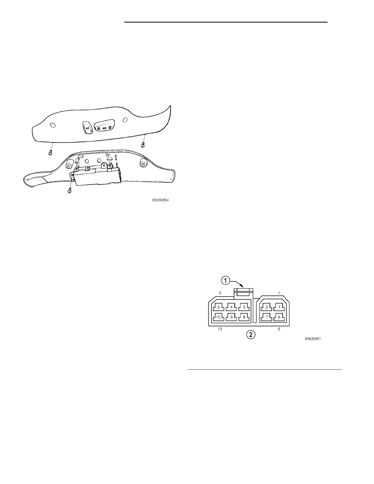
(4) To test the seat motors and verify proper seat
responses, refer to (Fig. 2) and the Seat Motor Test
table. Using two jumper wires, connect one to a bat-
tery supply and the second to a ground. Connect the
other ends to the seat wire harness connector as
described in the Seat Motor Test table.
Fig. 2 Power Seat Wire Harness Pin Call-Out
1 – BLUE
2 – VIEWED FROM TERMINAL END
Fig. 1 Power Seat Switch
8R - 2 POWER SEAT SYSTEMS LH
DESCRIPTION AND OPERATION (Continued)