HEADLAMP ADJUSTMENT
(Fig. 1). The low beam hot spot cut off should be
within 2 inches above/below the horizontal center
line, and to the right of the vertical center line. This
puts the low beam hot spot in the lower right quad-
rant of the aiming screen. Occasional stray filament
images should be disregarded while verifying aim.
Verify the vertical adjustment by checking the high
beams to ensure they are centered within 6 2 inches
relative to the horizontal center line. The low beams
should be shielded when checking high beams. Do
NOT cover the headlamp(s) for extended periods, as
the heat may damage them. To adjust headlamp
alignment, rotate the alignment screws, (Fig. 2) and
(Fig. 3) to achieve the specified pattern.
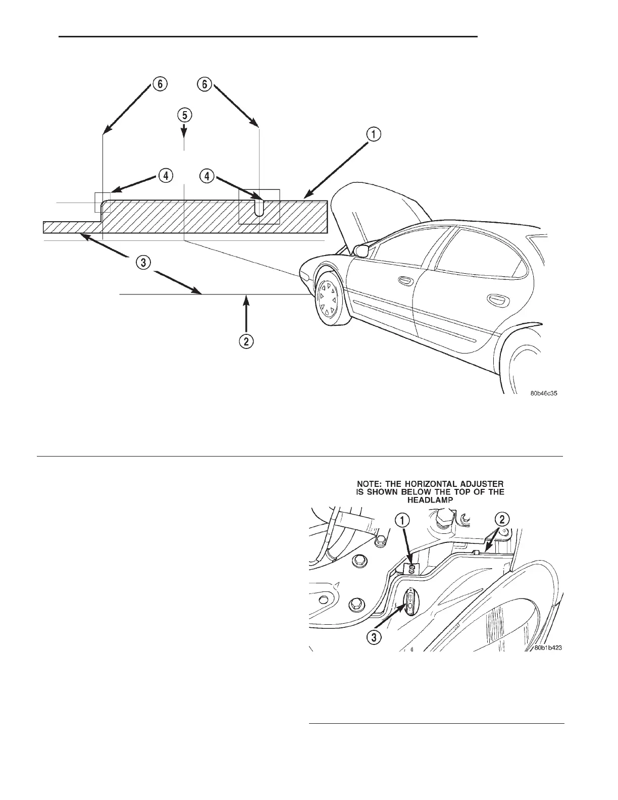
Fig. 1 Headlamp Alignment Screen
1 – LOW BEAM CENTER LINE TO GROUND
2 – FRONT OF HEADLAMP
3 – 7.26 METERS (25ft.)
4 – PREFERRED CUT OFF LOCATION 6 2 INS.
5 – CENTER OF VEHICLE
6 – CENTER OF HEADLAMP
Fig. 2 Headlamp Alignment Screws – Concorde/
LHS/300M
1 – VERTICAL ADJUSTER
2 – HORIZONTAL ADJUSTER
3 – BUBBLE LEVEL
LH LAMPS 8L - 9
ADJUSTMENTS (Continued)