SWITCH TEST
(1) Remove switch, refer to Switch Removal and
Installation in this section.
(2) Using an ohmmeter, perform the Seat Switch
Continuity Test table and (Fig. 3). If there is no con-
tinuity at any of the switch positions, replace switch.
VOLTAGE
The following test will determine whether or not
voltage is continuous through the body harness to
the switch.
(1) Remove power seat switch from mounting posi-
tion and disconnect switch from wiring harness.
(2) Using a voltmeter, connect the ground lead to
Pin 5 of the switch harness connector. Connect the
positive lead to Pin 1. If battery voltage the ground
and B+ circuit is OK. If no voltage check circuit
breaker and repair as necessary.
SEAT MOTOR TEST
SEAT CONNECTOR
CONNECT JUMPER SEAT ACTION
B (+) B (-) DRIVER
SIDE
PASSENGER
SIDE
PIN 9 PIN 6 FRONT
RISER UP
FRONT
RISER
DOWN
PIN 6 PIN 9 FRONT
RISER
DOWN
FRONT
RISER UP
PIN 10 PIN 3 FORWARD FORWARD
PIN 3 PIN 10 REARWARD REARWARD
PIN 8 PIN 7 REAR
RISER UP
REAR RISER
DOWN
PIN 7 PIN 8 REAR
RISER
DOWN
REAR RISER
UP
PIN 4 PIN 2 RECLINER
UP
RECLINER
UP
PIN 2 PIN 4 RECLINER
DOWN
RECLINER
DOWN
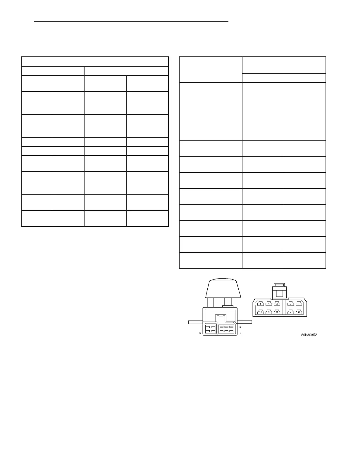
SEAT SWITCH CONTINUITY TEST
SWITCH POSITION CONTINUITY BETWEEN
PINS
DRIVER PASSENGER
OFF PIN 5 TO 4
PIN 5 TO 3
PIN 5 TO 2
PIN 5 TO 10
PIN 5 TO 9
PIN 5 TO 8
PIN 5 TO 7
PIN 5 TO 6
PIN 5 TO 4
PIN 5 TO 3
PIN 5 TO 2
PIN 5 TO 10
PIN 5 TO 9
PIN 5 TO 8
PIN 5 TO 7
PIN 5 TO 6
FRONT RISER UP PIN 5 TO 6
PIN 1 TO 9
PIN 5 TO 9
PIN 1 TO 6
FRONT RISER
DOWN
PIN 5 TO 9
PIN 1 TO 6
PIN 5 TO 6
PIN 1 TO 9
CENTER SWITCH
FORWARD
PIN 5 TO 3
PIN 1 TO 10
PIN 5 TO 3
PIN 1 TO 10
CENTER SWITCH
REARWARD
PIN 5 TO 10
PIN 3 TO 1
PIN 5 TO 10
PIN 3 TO 1
REAR RISER UP PIN 5 TO 7
PIN 1 TO 8
PIN 5 TO 8
PIN 1 TO 7
REAR RISER DOWN PIN 5 TO 8
PIN 1 TO 7
PIN 5 TO 7
PIN 1 TO 8
RECLINER UP PIN 5 TO 2
PIN 4 TO 1
PIN 5 TO 2
PIN 4 TO 1
RECLINER DOWN PIN 5 TO 4
PIN 2 TO 1
PIN 5 TO 4
PIN 2 TO 1
Fig. 3 Seat Switch Pin Call-Out
LH POWER SEAT SYSTEMS 8R - 3
DIAGNOSIS AND TESTING (Continued)