As the fluid drops below the designed level, the
switch closes completing the Red BRAKE Warning
Lamp circuit. This will illuminate the red BRAKE
warning lamp located in the instrument cluster. At
this time, the master cylinder fluid reservoir should
be checked and filled to the full mark with DOT 3
brake fluid. If the brake fluid level has dropped
in the brake fluid reservoir, the entire brake
hydraulic system should be checked for evi-
dence of a leak.
RED BRAKE WARNING LAMP
DESCRIPTION
The red BRAKE warning lamp is located in the
instrument cluster and is used to indicate a low
brake fluid condition or that the parking brake is
applied. In addition, the brake warning lamp is
turned on as a bulb check by the ignition switch
when the ignition switch is placed in the crank posi-
tion.
OPERATION
The red BRAKE warning lamp is supplied 12-volt
ignition feed anytime the ignition switch is on. The
lamp is then illuminated by completing the ground
circuit either through the parking brake warning
switch mounted on the parking brake lever, the
brake fluid level switch mounting in the master cyl-
inder reservoir, or the ignition switch when in the
crank position. The red BRAKE lamp can also be
illuminated by the instrument cluster in the case
when the ABS CAB detects a fault in the ABS sys-
tem and cannot illuminate the amber ABS warning
lamp.
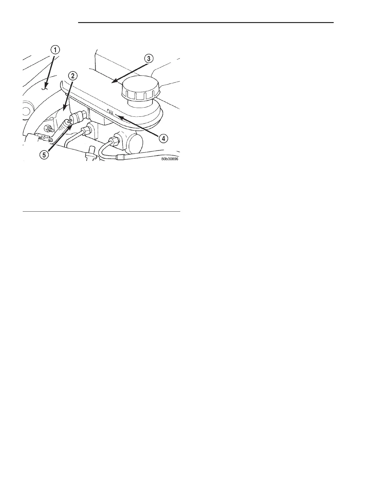
Fig. 14 Brake fluid Level Switch (Sensor)
1 – BOOSTER
2 – MASTER CYLINDER
3 – MASTER CYLINDER FLUID RESERVOIR
4 – FLUID LEVEL FULL MARK
5 – FLUID LEVEL SENSOR
5 - 10 BRAKES LH
DESCRIPTION AND OPERATION (Continued)