(6) Remove the 4 bolts attaching both stabilizer
bar isolator bushing retainers to the frame rails (the
2 rearward attaching bolts also attach the front cor-
ners of the rear suspension crossmember in place).
Allow the stabilizer bar to hang down out of the way.
(7) Remove the screw securing the fuel filler neck
to the left frame rail.
(8) Position a transmission jack under the fuel
tank.
(9) Remove the attaching bolts securing both fuel
tank mounting straps. First, remove the right, then
the left attaching bolt. Allow the straps to hang
down.
(10) Lower the transmission jack and fuel tank
just enough to allow for removal of the lateral link
attaching bolt at the crossmember.
(11) Remove the left forward lateral link from the
crossmember.
INSTALL
CAUTION: The bolts attaching the forward lateral
links to the crossmember must be installed with the
bolts pointing rearward (Fig. 25) to prevent damage
to the fuel tank and or fuel tubes. Also, the left rear
lateral arm attaching bolt to the crossmember is to
be installed pointing forward to prevent possible
damage to the fuel filler tube.
(1) Attach the left forward lateral link to cross-
member. Install mounting bolt through the front of
the crossmember mount towards the rear. Install the
lateral link attaching nut, but DO NOT fully tighten
at this time.
CAUTION: Tightening the lateral link attaching bolt
at this point will cause the bushing to contort when
the vehicle is at curb riding height, thus contribut-
ing to premature failure of the lateral link bushings.
(2) Raise the fuel tank up into mounting position.
(3) Reattach the fuel tank straps, securing the fuel
tank in place.
(4) Remove transmission jack supporting the fuel
tank.
(5) Reinstall the fuel filler neck attaching screw
and secure the fuel filler neck to the left frame rail.
(6) Install the 4 bolts attaching both stabilizer bar
isolator bushing retainers to the frame rails (the 2
rearward attaching bolts attach the front corners of
the rear suspension crossmember in place). Tighten
the forward stabilizer bar isolator bushing retainer
attaching bolts to 40 N·m (30 ft. lbs.). Tighten the 2
rearward stabilizer bar isolator bushing retainer
attaching bolts (which also serve as the front cross-
member attaching bolts) to 100 N·m (75 ft. lbs.).
(7) Install the screw securing the brake tubes to
the left stabilizer bar isolator bushing retainer.
(8) Install the lateral links on the spindle. Install,
but DO NOT fully tighten the attaching bolt and nut
at this time (Fig. 24).
CAUTION: Tightening the lateral link attaching bolt
at this point will cause the bushing to contort when
the vehicle is at curb riding height, thus contribut-
ing to premature failure of the lateral link bushings.
(9) Install rear wheel and tire assembly on vehicle.
(10) Tighten the wheel mounting stud nuts in
proper sequence until all nuts are torqued to half
specification. Then repeat the tightening sequence to
the full specified torque of 129 N·m (95 ft. lbs.).
(11) Lower vehicle to the ground.
(12) Tighten lateral arm to crossmmember attach-
ing bolt 95 N·m (70 ft. lbs.).
(13) Tighten lateral arm to spindle attaching bolt
135 N·m (100 ft. lbs.).
(14) Check and reset rear wheel TOE to specifica-
tions if required.
LEFT REAR AND BOTH RIGHT LATERAL LINKS
REMOVE
(1) Raise vehicle on jackstands or centered on a
frame contact type hoist. See Hoisting in the Lubri-
cation and Maintenance section of this manual, for
the required lifting procedure to be used for this
vehicle.
(2) Remove rear wheel and tire assembly from the
vehicle.
(3) Remove the nut and bolt attaching the left lat-
eral links to the spindle (Fig. 26).
(4) Remove the nut and bolt attaching the lateral
link to the rear suspension crossmember. Note the
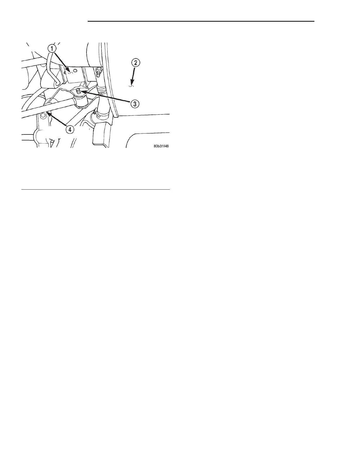
Fig. 25 Lateral Link Attachment To Crossmember
1 – CROSSMEMBER
2 – EXHAUST MUFFLER
3 – ATTACHING BOLT
4 – LEFT FORWARD LATERAL LINK
2 - 56 SUSPENSION LH
REMOVAL AND INSTALLATION (Continued)