DESCRIPTION AND OPERATION
COOLING SYSTEM
DESCRIPTION
The cooling system consists of an engine cooling
module, pressure cap, coolant bottle, thermostat
(inlet), coolant, plumbing, and a water pump to cir-
culate the coolant (Fig. 1). The engine cooling module
consist of a radiator, electric fan motors, shroud,
internal transmission oil cooler, internal engine oil
cooler (if equipped), air conditioning condenser, and a
auxiliary transmission oil cooler (if equipped).
OPERATION
• When Engine is cold: Thermostat is closed, cool-
ing system has no flow through the radiator. The
coolant flows through the engine heater core, coolant
bottle and an internal engine by-pass.
• When Engine is warm: Thermostat is open, cool-
ant flows through the radiator, heater core, coolant
bottle and by-pass.
The cooling systems primary purpose is to main-
tain engine temperature in a range that will provide
satisfactory engine performance and emission levels
under all expected driving conditions. It also provides
hot coolant for heater, and cooling for automatic
transmission fluid. It does this by transferring heat
from engine metal to coolant, moving this heated
coolant to the radiator, and then transferring this
heat to the ambient air.
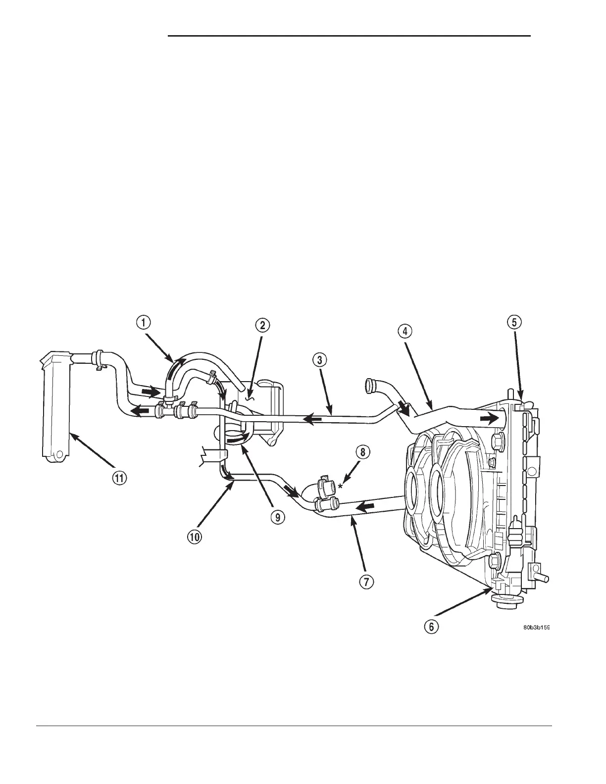
The coolant flow circuit is shown in (Fig. 1).
Fig. 1 Cooling System Flow
1 – BOTTLE SUPPLY HOSE
2 – PRESSURE BOTTLE
3 – HEATER SUPPLY TUBE
4 – RADIATOR UPPER INLET HOSE
5 – RADIATOR
6 – DRAIN COCK
7 – RADIATOR LOWER OUTLET HOSE
8 – THERMOSTAT LOCATION
9 – BOTTLE RETURN
10 – HEATER RETURN TUBE
11 – HEATER CORE
7 - 2 COOLING SYSTEM LH