front side. A small molded plastic protective cover on
the front right side of the engine compartment is
unsnapped to access the battery/generator cable
input connection studs.
OPERATION
All of the PDC outputs are through the integral
engine compartment wire harness, which exits from
the front of the PDC housing.
All of the current from the battery/generator cable
connection enters the PDC through a 140 ampere
fusible link that is secured with screws just inside
the left end of the PDC housing. The PDC houses up
to fourteen maxi-fuse cartridges, which replace all in-
line fusible links. The PDC also houses up to six
blade-type fuses, up to four full International Stan-
dards Organization (ISO) relays, and up to seven ISO
micro-relays. Internal connection of all the PDC cir-
cuits is accomplished by an intricate network of hard
wiring and bus bars. Refer to Power Distribution
in the Component Index of Group 8W - Wiring Dia-
grams for complete circuit diagrams.
The fusible link, fuse cartridges, fuses and relays
are available for service replacement. The PDC unit
cannot be repaired and is only serviced as a unit
with the engine compartment wire harness. If the
PDC is faulty or damaged, the engine compartment
wire harness assembly must be replaced.
JUNCTION BLOCK (JB)
DESCRIPTION
An electrical Junction Block (JB) is located in the
left endcap of the instrument panel. The JB combines
the functions previously provided by a separate fuse-
block module and relay center. It also serves to sim-
plify and centralize numerous electrical components,
as well as to distribute electrical current to many of
the accessory systems in the vehicle. It eliminates
the need for numerous splice connections and serves
in place of a bulkhead connector between many of
the engine compartment, instrument panel, and body
wire harnesses.
The JB is positioned on a mounting bracket up and
under the left instrument panel. It is secured by four
screws. The JB is concealed behind the left instru-
ment panel endcap. The left instrument panel endcap
is a snap-fit fuse access cover that conceals the JB
fuses. A fuse puller and spare fuse holders are
located on the back of the endcap, as well as the fuse
layout to ensure proper fuse identification. The left
instrument panel endcap must be removed to access
components other than the fuses in the JB.
OPERATION
All of the current entering and leaving the JB does
so through wire harnesses, which are connected to
the JB through integral connector receptacles molded
into the JB housing. The JB houses blade-type fuses,
blade-type automatic resetting circuit breakers, full
International Standards Organization (ISO) relays,
and ISO micro-relays. Internal connection of all the
JB circuits is accomplished by an intricate network of
hard wiring and bus bars. Refer to Junction Block
in the Component Index of Group 8W - Wiring Dia-
grams for complete circuit diagrams.
The fuses, circuit breakers, relays, and are avail-
able for service replacement. The JB unit cannot be
repaired and is only serviced as an assembly. If any
internal circuit or the JB housing is faulty or dam-
aged, the entire Junction Block assembly must be
replaced.
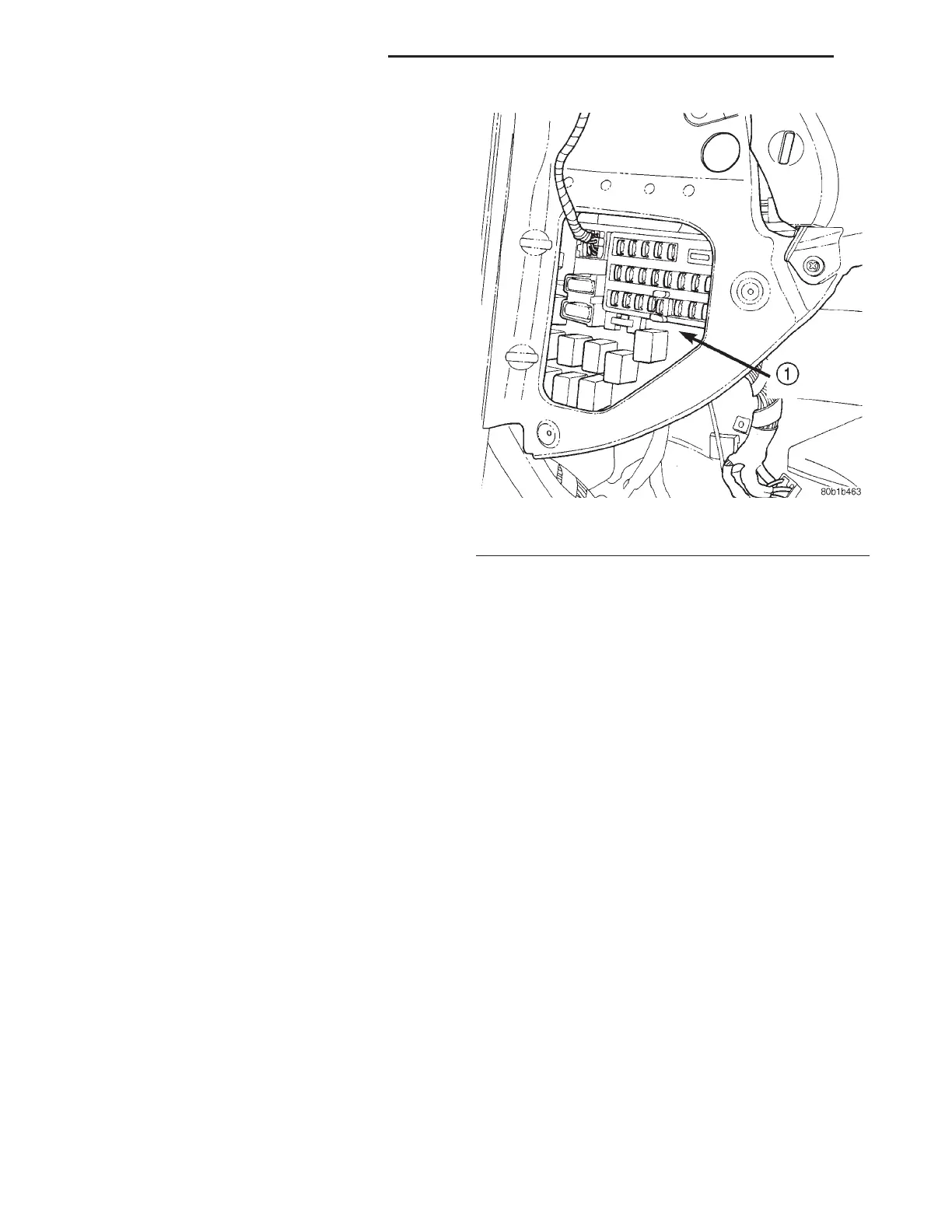
Fig. 2 Junction Block Location
1 – JUNCTION BLOCK/BCM
8O - 2 POWER DISTRIBUTION SYSTEMS LH
DESCRIPTION AND OPERATION (Continued)