WIPER AND WASHER SYSTEMS
TABLE OF CONTENTS
page page
DESCRIPTION AND OPERATION
WINDSHIELD WIPER SYSTEM ..............1
WINDSHIELD WASHER SYSTEM.............2
WIPER BLADES ..........................2
DIAGNOSIS AND TESTING
INTERMITTENT WIPER FUNCTION ...........2
MULTI-FUNCTION/WIPER SWITCH ...........2
WINDSHIELD WASHERS ...................3
WINDSHIELD WIPER SYSTEM CONDITIONS ...6
WIPER MOTOR SYSTEM ...................8
REMOVAL AND INSTALLATION
MULTI-FUNCTION SWITCH ................12
WASHER FLUID LEVEL SENSOR............13
WASHER FLUID LEVEL SENSOR (INTREPID) . . 13
WASHER HOSE .........................13
WINDSHIELD WASHER NOZZLES ...........14
WASHER RESERVOIR ....................14
WASHER RESERVOIR (INTREPID) ..........14
WASHER RESERVOIR FILLER TUBE .........15
WASHER RESERVOIR PUMP...............15
WIPER ARM AND BLADE..................16
WIPER BLADE ..........................16
WIPER BLADE ELEMENT ..................16
WIPER FRAME ASSEMBLY ................17
WIPER LINK ARMS ......................18
WIPER MOTOR..........................18
CLEANING AND INSPECTION
WIPER BLADES .........................19
ADJUSTMENTS
WASHER NOZZLE........................19
WIPER ARM ADJUSTMENT ................19
DESCRIPTION AND OPERATION
WINDSHIELD WIPER SYSTEM
WARNING: VEHICLES ARE EQUIPPED WITH AN
AIRBAG, REFER TO GROUP 8M, RESTRAINT SYS-
TEMS FOR STEERING WHEEL OR COLUMN SER-
VICE PROCEDURES.
DESCRIPTION
The windshield wiper system is controlled by a
switch located on the multi-functin switch stalk. The
multi-function switch is located on the steering col-
umn behind the steering wheel.
OPERATION
The windshield wipers will operate when the igni-
tion switch is in the ACCESSORY or IGNITION ON
position. The windshield wipers will return to the
parked position when the ignition switch is turned to
the OFF position. Fuses, located in the Junction
Block and Power Distribution Center protects the cir-
cuitry of the wiper system and the vehicle.
The wiper motor has permanent magnet fields. The
speeds are determined by current flow to the appro-
priate set of brushes.
The intermittent wiper system, in addition to low
and high speed, has a delay mode. The delay mode
has a range of 1/2 to 18 seconds. The wiper delay
times will double to a range of 1 to 36 seconds when
the vehicle speed is less than 10 mph. The delay is
controlled by a variable resistor in the wiper switch
and the Body Control Module (BCM). The BCM con-
trols the timing for the wiper ON/OFF, as well as the
wiper HI/LO relay.
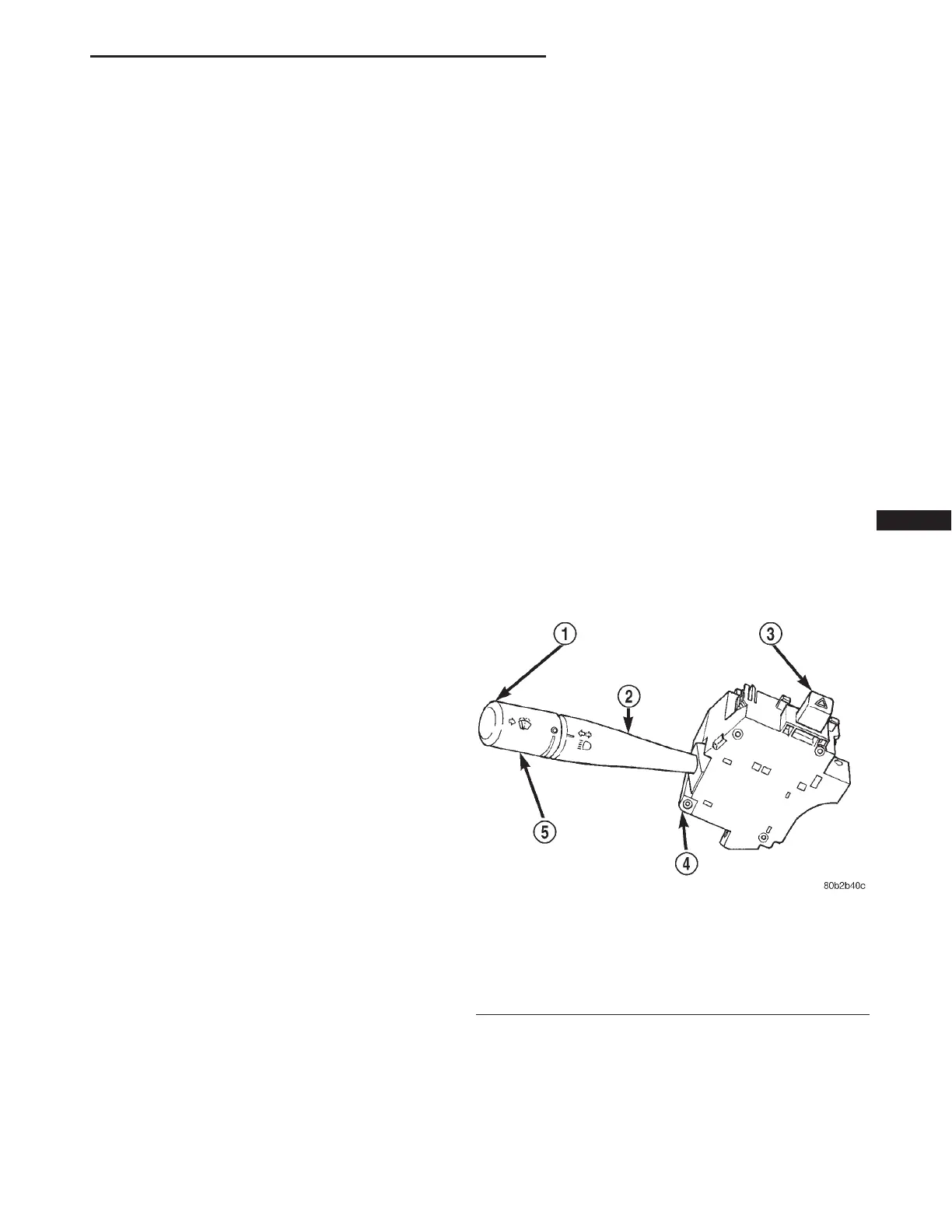
Fig. 1 Windshield Wiper Switch
1 – WINDSHIELD WASHER BUTTON
2 – CONTROL STALK (BEAM SELECT)
3 – HAZARD WARNING BUTTON
4 – MULTI-FUNCTION SWITCH
5 – WINDSHIELD WIPER CONTROL
LH WIPER AND WASHER SYSTEMS 8K - 1