Cluster and Bezel Removal and Installation in this
section.
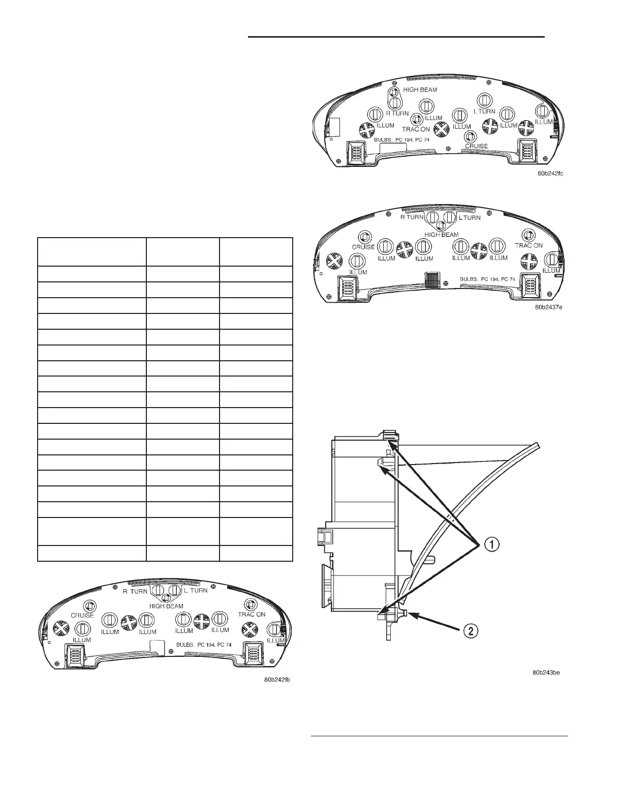
Refer to (Fig. 14), (Fig. 15), and (Fig. 16) for cluster
lamp locations.
The lamps that are replaceable are called out on
the back cover of the instrument cluster. All other
indicators are Light Emitting Diodes (LED’s), and
are serviced with the cluster assembly. If a LED is
non-functional, the entire instrument cluster must be
replaced. Refer to the INDICATORS – BULBS table
for applications.
CLUSTER MASK/LENS
The instrument cluster must be removed for mask/
lens service. Refer to Instrument Cluster and Bezel
Removal and Installation in this section.
REMOVAL
(1) Open hood and disconnect the negative battery
cable remote terminal from the remote battery post
(Fig. 22).
(2) Remove instrument cluster from vehicle. Refer
to procedures in this section.
(3) Remove two screws to mask/lens (Fig. 17).
INDICATORS – BULBS
INDICATOR COLOR BULB # /
LED
BATTERY RED LED
BRAKE RED LED
AIRBAG RED LED
LOW OIL RED LED
SEATBELT RED LED
TEMPERATURE RED LED
DOOR AJAR RED LED
DECKLID AJAR RED LED
HIGH BEAM BLUE 74
TURN SIGNALS GREEN 194
CRUISE GREEN 74
TRAC ON GREEN 74
TRAC OFF AMBER LED
CHECK ENGINE AMBER LED
ABS AMBER LED
LOW FUEL AMBER LED
LOW WASHER
FLUID
AMBER LED
ILLUMINATION BLUEGREEN 194
Fig. 14 Cluster lamps – Intrepid
Fig. 15 Cluster lamps – Concorde
Fig. 16 Cluster Lamps – LHS / 300M
Fig. 17 Instrument Cluster Mask/Lens Retaining
Screws
1 – MASK/LENS RETAINING TABS
2 – RETAINING SCREWS
8E - 12 INSTRUMENT PANEL SYSTEMS LH
REMOVAL AND INSTALLATION (Continued)
 Loading...


