(6) If necessary, repeat steps 2 through 5 to the
other side of the vehicle.
(7) Lower the vehicle.
(8) Jounce the front and rear of vehicle.
(9) Adjust the front camber to the preferred set-
ting by pushing in or pulling outward on the top of
the wheel and tire as required. When camber is cor-
rect, tighten the upper and lower strut to knuckle
camber adjustment bolts to a torque of 170 N·m (125
ft. lbs.).
(10) Proceed to Front Wheel Toe Adjustment in
this section and adjust front wheel toe as necessary.
FRONT WHEEL TOE ADJUSTMENT
(1) Center steering wheel and hold it in place
using a steering wheel clamp.
(2) Loosen the tie rod adjustment pinch bolt.
Rotate the adjustment sleeve to align toe to specifi-
cations (Fig. 7).
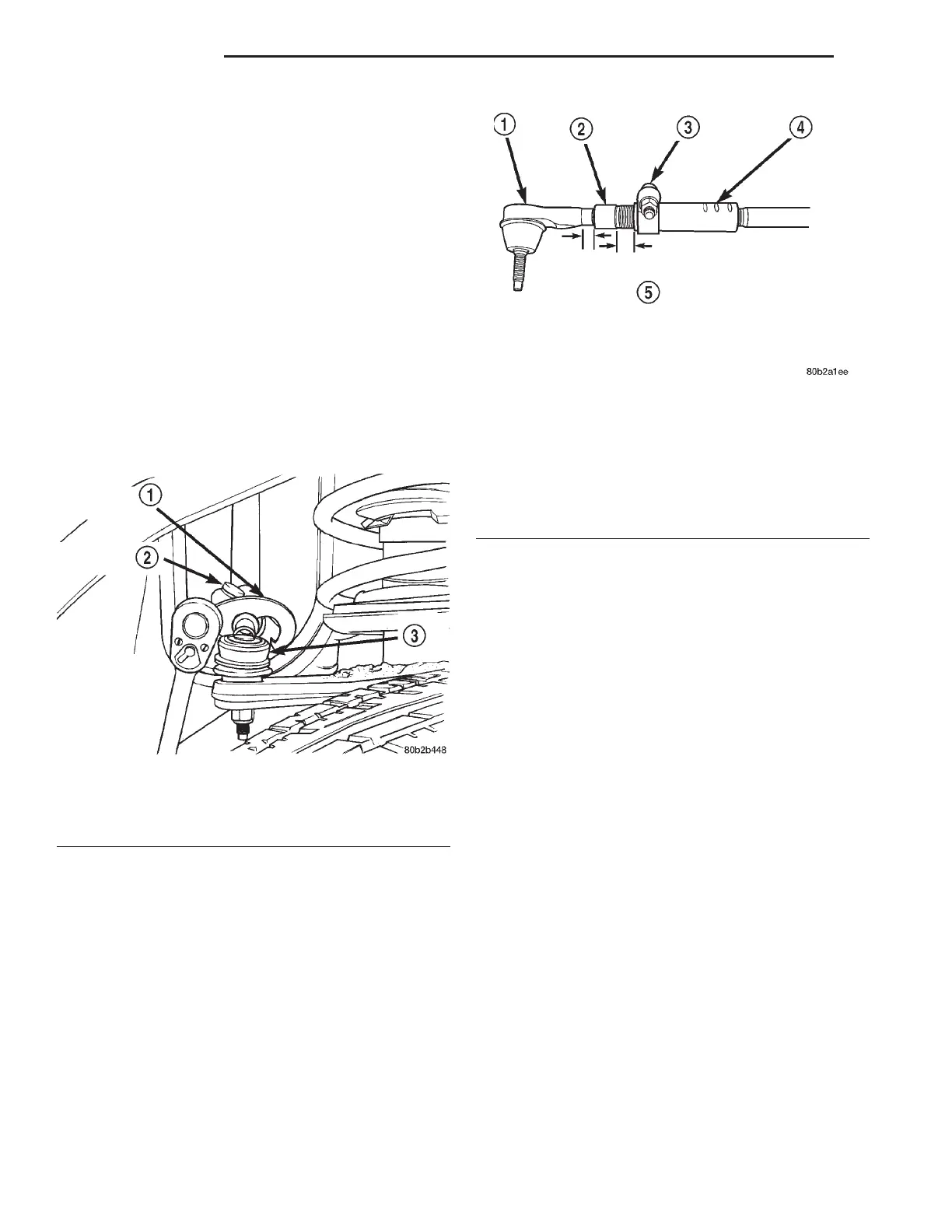
CAUTION: When setting toe on vehicle, the maxi-
mum dimension of exposed threads allowed on
inner and outer tie rod cannot exceed the distance
shown (Fig. 8). If the maximum distance is
exceeded, inadequate retention of either inner or
outer tie rod may result. Ensure that adjustment
pinch bolt is torqued to required specification when
Toe setting procedure is completed.
CAUTION: When torquing adjustment pinch bolt,
the following procedure must be followed to ensure
adequate retention of the adjustment sleeve. Not
following this procedure, could result in the Toe
Setting Adjustment changing and/or loosening of
the inner or outer tie rod ends.
NOTE: Use an appropriate tool on neck area of
outer tie rod to maintain the correct perpendicular
orientation of the tie rod end stud within the tie rod
end.
(3) After completion of toe adjustment procedure,
tighten tie rod pinch bolt (Fig. 8) to a torque of 38
N·m (28 ft. lbs.).
(6) Road test the vehicle after the initial wheel
alignment has been performed. If vehicle still drifts
or leads, repeat the front wheel alignment procedure
and adjust the camber to bias the cross camber set-
ting opposite of the direction in which the vehicle has
the tendency to lead. For example, if the vehicle
leads left, compensate by setting left front camber to
0.0° and right front camber up to +0.6°, allowing
both sides to remain within camber specifications.
The cross camber is still at 0.6° which is within the
allowed alignment specification.
Fig. 7 Front Wheel Toe Adjustment Location
1 – ADJUSTMENT TOOL
2 – ADJUSTMENT PINCH BOLT
3 – TIE ROD END
Fig. 8 Tie Rod Thread Engagement Requirements
1 – OUTER TIE ROD
2 – ADJUSTER
3 – PINCH BOLT
4 – INNER TIE ROD
5 – ALLOWABLE THREADS EXPOSED ON OUTER TIE ROD
AND ADJUSTER IS A MAXIMUM OF 20 MILLIMETERS.
REFER TO AREA INDICATED ABOVE ON THE OUTER TIE
ROD AND ADJUSTER.
2 - 8 SUSPENSION LH
SERVICE PROCEDURES (Continued)