(Fig. 14). Then remove hub and bearing assembly
from spindle.
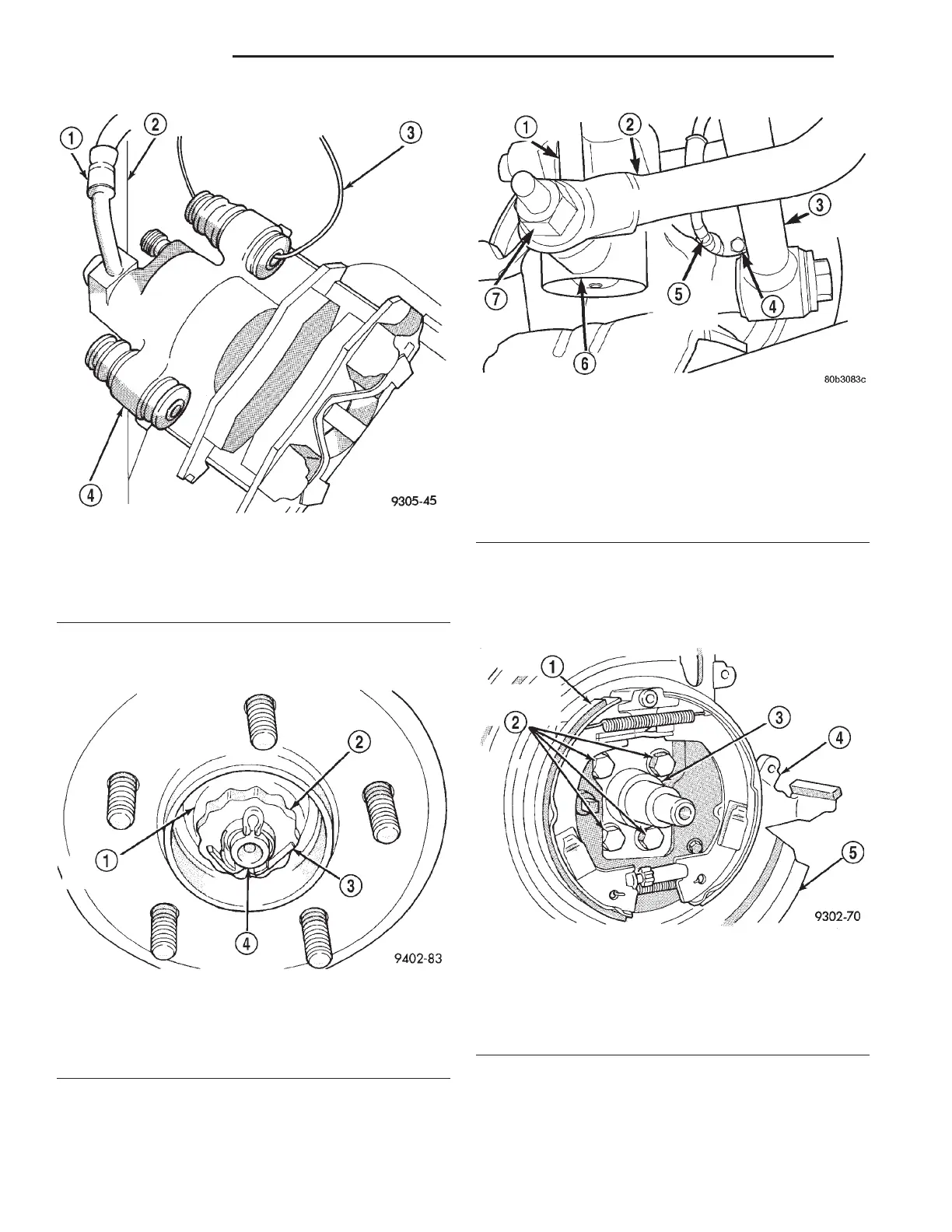
(6) If vehicle is equipped with antilock brakes,
remove the speed sensor head from the rear disc
brake adapter (Fig. 15).
(7) Remove the 4 bolts attaching the disc brake
adapter to the rear spindle (Fig. 16). Then remove
the adapter, disc shield, park brake shoes and park
brake cable as an assembly from the spindle.
(8) Remove the bolt attaching the trailing arm to
the bracket on the bottom of the spindle (Fig. 17).
(9) Remove the bolt (Fig. 18) attaching the lateral
links to the spindle.
Fig. 13 Storing Caliper
1 – FLEX HOSE
2 – STRUT
3 – WIRE HANGER
4 – CALIPER ASSEMBLY
Fig. 14 Hub And Bearing Retaining Nut and Washer
1 – HUB RETAINING NUT
2 – NUT RETAINER
3 – COTTER PIN
4 – SPINDLE
Fig. 15 Speed Sensor Head
1 – STABILIZER BAR LINK
2 – STABILIZER BAR
3 – LATERAL LINK
4 – BOLT
5 – WHEEL SPEED SENSOR
6 – STRUT ASSEMBLY
7 – NUT
Fig. 16 Disc Brake Adapter Mounting
1 – PARK BRAKE SHOES
2 – ADAPTER MOUNTING BOLTS
3 – SPINDLE
4 – ADAPTER
5 – DISC SHIELD
2 - 52 SUSPENSION LH
REMOVAL AND INSTALLATION (Continued)