(4) Lubricate O-ring and insert heater tube assem-
bly into outlet connector. Tighten screws to 3 N·m (30
in. lbs.).
(5) Install upper intake manifold. Refer to
ENGINE for procedure.
(6) Fill cooling system. Refer to Cooling System
Filling in this section.
HEATER SUPPLY TUBE—2.7L
REMOVAL
WARNING: DO NOT REMOVE PRESSURE CAP
WITH THE SYSTEM HOT AND UNDER PRESSURE
BECAUSE SERIOUS BURNS FROM COOLANT CAN
OCCUR.
(1) Drain cooling system. Refer to procedure in
this section.
(2) Remove upper radiator crossmember. Refer to
BODY for procedure.
(3) Remove upper radiator hose at tube.
(4) Remove heater hose from heater tube at rear of
engine.
(5) Disconnect heater tube from retaining clip at
rear of engine.
(6) Disconnect electrical connector from coolant
temperature sensor.
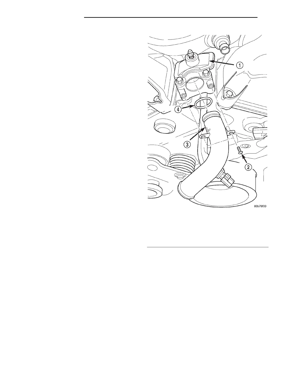
(7) Remove screws attaching heater tube to outlet
connector (Fig. 28).
(8) Disengage heater tube from outlet connector
(Fig. 28). To remove heater tube, move forward until
the tube clears cylinder heads.
INSTALLATION
(1) Inspect heater tube O-ring. Replace as neces-
sary.
(2) Lubricate O-ring and install heater tube by
inserting tube in-between cylinder heads. Insert tube
into water outlet housing (Fig. 28).
(3) Attach heater tube to the retaining clip at rear
of engine.
(4) Install attaching screws and tighten to 3 N·m
(30 in. lbs.).
(5) Install upper radiator hose and heater hose to
heater tube.
(6) Connect electrical connector to coolant temper-
ature sensor.
(7) Install upper radiator crossmember. Refer to
BODY for procedure.
(8) Fill cooling system. Refer to Cooling System
Filling in this section.
HEATER SUPPLY TUBE—3.2/3.5L
REMOVAL
WARNING: DO NOT REMOVE PRESSURE CAP
WITH SYSTEM HOT AND UNDER PRESSURE
BECAUSE SERIOUS BURNS FROM COOLANT CAN
OCCUR.
(1) Drain cooling system. Refer to procedure in
this section.
(2) Remove upper and lower intake manifold.
Refer to ENGINE for procedures.
(3) With lower intake manifold turned upside
down on bench, remove the tube retaining bolt.
(4) Remove tube from manifold and discard O-ring.
Fig. 28 Heater Supply Tube—Removal and
Installation
1 – OUTLET CONNECTOR
2 – SCREW (2)
3 – HEATER TUBE
4 – O-RING
7 - 24 COOLING SYSTEM LH
REMOVAL AND INSTALLATION (Continued)