on the locking latch and disconnect the ORC 23-way
connector.
(11) Remove the two side module mounting screws
on the drivers side.
(12) Loosen the top screw on the drivers side.
(13) Lift up the module and slide out the ORC.
NOTE: If the module cannot be lifted out, the pas-
senger side screw needs some additional loosen-
ing.
(14) Remove the ORC from vehicle.
INSTALLATION
WARNING: THE ORC IS A SAFETY MODULE AND
FAILURE TO INSTALL AND SECURE IT PROPERLY,
COULD CAUSE THE MODULE TO POSSIBLY MAL-
FUNCTION.
(1) Position the ORC (arrow pointing forward in
vehicle) on the ORC mounting bracket. The mounting
bosses on the module will correctly position the ORC
on the bracket. Attach the ORC to the bracket with
the three screws supplied and torque to 88 to 124
in.lbs. (10 to 14 N·m).
CAUTION: USE SUPPLIED SCREWS ONLY.
(2) Reverse the above procedures for continued
installation.
CAUTION: Do not connect negative battery cable
remote terminal. Refer to Airbag System Check in
this section for proper procedure.
PASSENGER AIRBAG MODULE
NON DEPLOYED MODULE
When removing a module for any reason other
than DEPLOYMENT.
The instrument panel must be PARTIALLY
removed for Passenger Airbag Module service. Refer
to Group 8E, Instrument Panel and Systems for
graphics of complete I/P.
REMOVAL
(1) Open hood and disconnect the negative battery
cable remote terminal from the remote battery post.
(2) Remove the four screws that attach the glove
box door to the instrument panel and remove the
glove box door.
(3) Remove right instrument panel endcap.
(4) If equipped with center console:
• Remove the gearshift handle set screw and then
remove the gear shift handle.
• Remove the console shifter bezel.
• Remove the right console side trim panel.
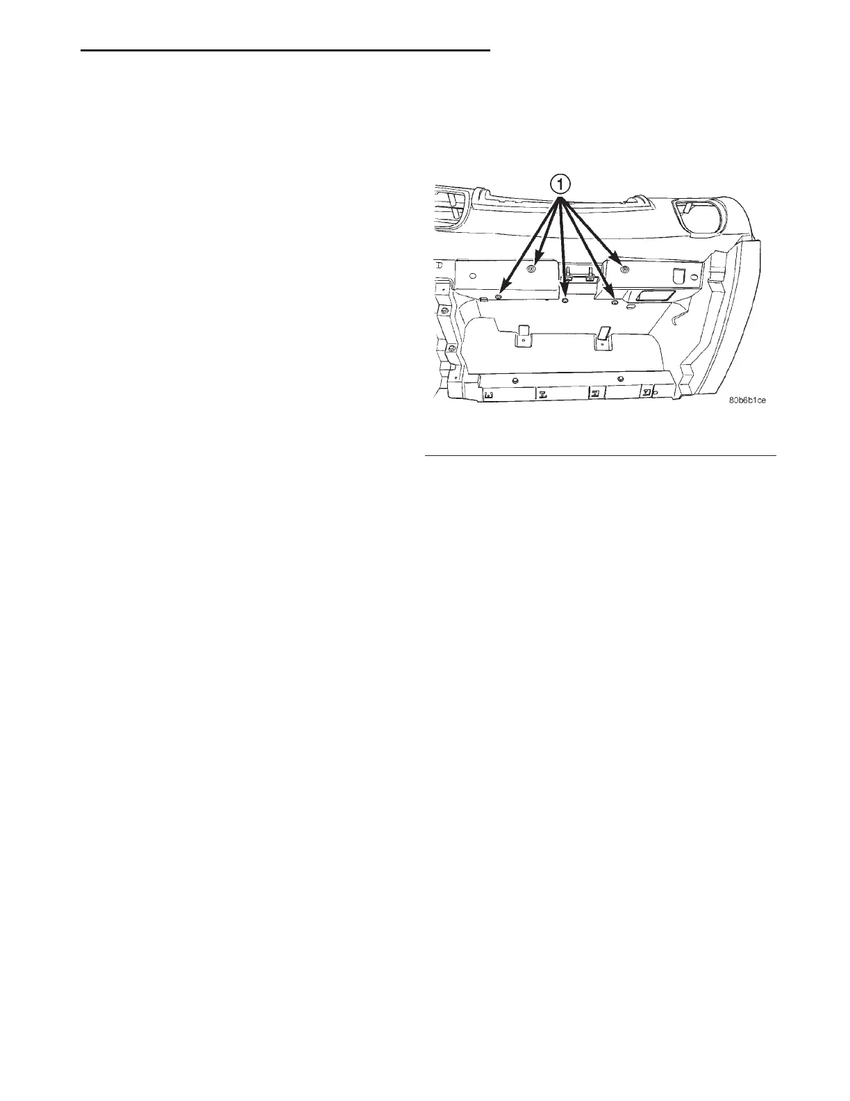
(5) Accessing through the glove box door, remove
five screws to the glove box close-out assembly (20 in.
lbs. torque) (Fig. 6).
(6) Remove the left and right A-pillar trim mold-
ings.
(7) Remove the left instrument panel endcap.
(8) Remove the left lower instrument panel trim
cover. Disconnect the hood release cable and decklid
release electrical connector. Remove and set panel
aside.
(9) Remove the left knee blocker.
(10) Remove the instrument panel center bezel.
Disconnect the heater - a/c control unit and traction
control switch (if equipped), electrical connectors.
(11) If equipped with console, remove the left
instrument panel side cover.
(12) If not equipped with center console, remove
the center lower instrument panel floor bin.
(13) Remove the two center instrument panel
lower attaching nuts.
(14) Remove the left (driver’s) side air distribution
ducts.
(15) Disconnect the brake switch electrical connec-
tor.
(16) Remove the bulkhead connector mounting
screw.
NOTE: It is not necessary to disconnect the bulk-
head connector.
(17) Disconnect the Occupant Restraint Controller
(ORC) electrical connector.
(18) Disconnect the two center instrument panel
ground eyelets on the left side of the floor tunnel.
(19) Remove the four steering column nuts and
lower the steering column to the floor.
Fig. 6 Glove Box Close - Out to Reinforcement
1 – RETAINING SCREWS
LH PASSIVE RESTRAINT SYSTEMS 8M - 7
REMOVAL AND INSTALLATION (Continued)