The wiper system completes the wipe cycle when
the switch is turned OFF. The blades park in the
lowest portion of the wipe pattern.
When using the DRB lllt scan tool, refer to the
proper Body Diagnostic Procedures Manual for Diag-
nosis and Testing.
WINDSHIELD WASHER SYSTEM
DESCRIPTION
All models are equipped with electric operated
windshield washer pumps. The electric pump assem-
bly is mounted with a grommet directly to the reser-
voir.
The windshield washer system is controlled by a
switch located on the multi-functin switch stalk. The
multi-function switch is located on the steering col-
umn behind the steering wheel.
OPERATION
The wash function can be accessed in the OFF
position of the wiper control switch. Wash switch
must be pressed for at least 0.5 second to get the
wipe after wash. Holding the wash button depressed
when the switch is in the OFF position will operate
the wipers and washer motor pump continuously
until the washer button is released. Releasing the
button will stop the washer pump but the wipers will
complete the current wipe cycle, followed by an aver-
age of two more wipe cycles (61) before the wipers
park and the module turns off. If the wash switch is
pressed momentarily with the wipers in the OFF or
INTERMITTENT position, a pulse wipe cycle consist-
ing of two wipes will occur.
Fluid is gravity fed from the reservoir to the motor.
The fluid is forced by the pump through rubber hoses
to the hood mounted nozzles which direct the fluid
streams to the windshield. The one way flow check
valves are located in each hood nozzle. The purpose
of the check valves is to improve fluid flow response
time and to prevent excessive washer fluid staining
the surface of the hood. The hood mounted nozzles
distribute washer fluid on the surface of the wind-
shield. The nozzles are adjustable, refer to the
Washer Nozzle Adjusting Procedures. The pump and
reservoir are serviced as separate assemblies.
WIPER BLADES
DESCRIPTION
The wiper blades are a rubber element with a steel
vertebrae that are mounted on the end of the wind-
shield wiper arm and sweep across the front wind-
shield to clear it of water, snow, and debris.
OPERATION
When the wiper blade rubber element is exposed to
the weather for a long period of time, it tends to lose
wiping ability. Periodic cleaning of the wiper blade
element is suggested to remove the accumulation of
salt and road film. The wiper blades, arms, and
windshield should be cleaned with a sponge or cloth
and a mild detergent or non-abrasive cleaner. If the
blades continue to streak or smear, they should be
replaced. The driver blade element is 600 mm in
length and the passenger blade element is 550 mm in
length.
DIAGNOSIS AND TESTING
INTERMITTENT WIPER FUNCTION
WARNING: ON VEHICLES EQUIPPED WITH AIR-
BAGS, SEE GROUP 8M, RESTRAINT SYSTEMS FOR
STEERING WHEEL OR COLUMN REMOVAL PROCE-
DURES.
The intermittent wiper function is controlled by
the Body Control Module (BCM), located in the left
side of the instrument panel, attached to the Junc-
tion Block (Fig. 3). If the Body Control Module is
determined to be the problem, refer to Group 8E,
Instrument Panels and Systems, for replacement pro-
cedures.
MULTI-FUNCTION/WIPER SWITCH
To test the multi-function/wiper switch, first dis-
connect the switch wires from the body wiring in the
steering column (Fig. 4). Using an ohmmeter, test for
continuity between the terminals of the switch, as
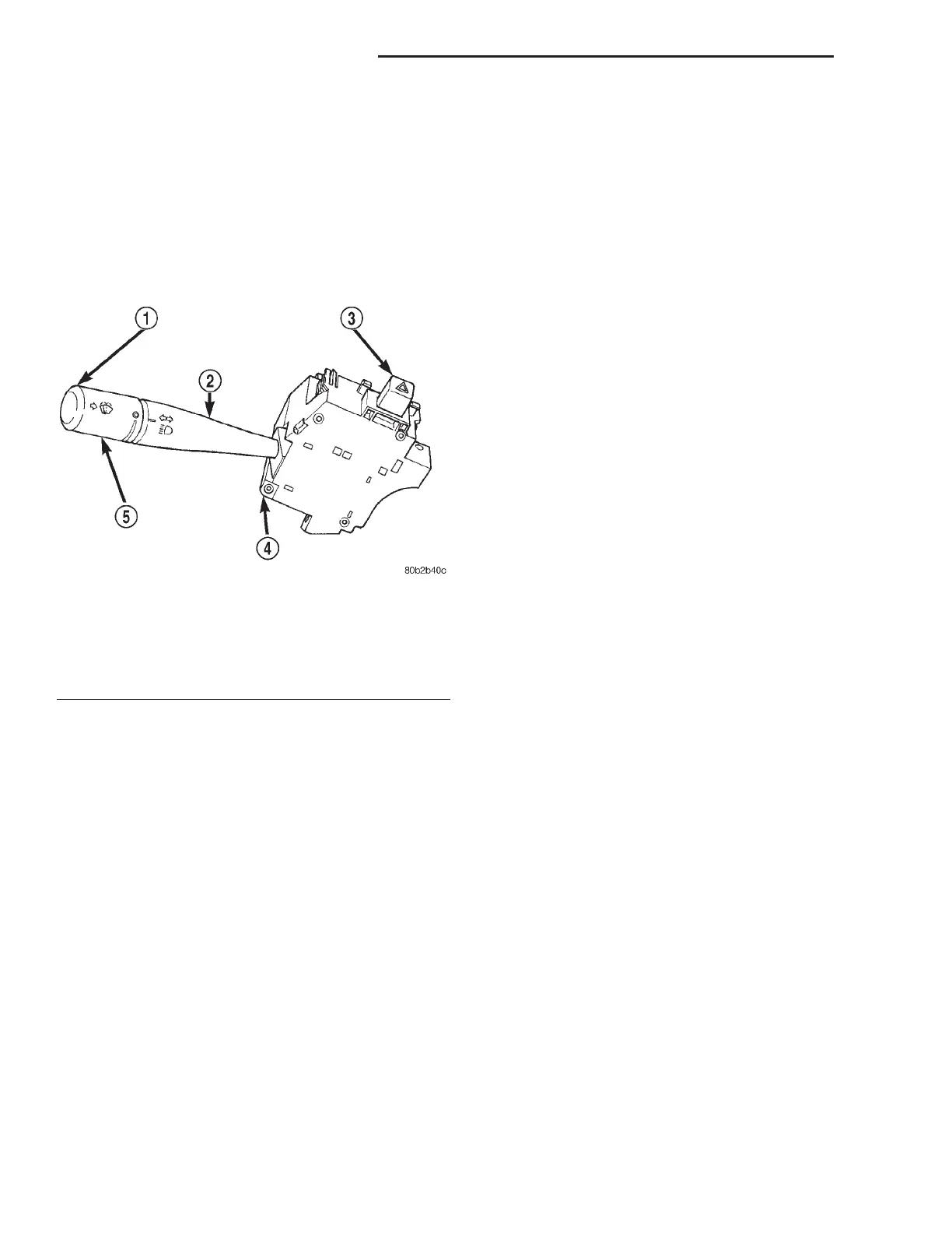
Fig. 2 Windshield Washer Switch
1 – WINDSHIELD WASHER BUTTON
2 – CONTROL STALK (BEAM SELECT)
3 – HAZARD WARNING BUTTON
4 – MULTI-FUNCTION SWITCH
5 – WINDSHIELD WIPER CONTROL
8K - 2 WIPER AND WASHER SYSTEMS LH
DESCRIPTION AND OPERATION (Continued)