SUPPLY CIRCUIT AND CONTROL CIRCUIT
DESCRIPTION
The starter system consists of two separate cir-
cuits (Fig. 1).
OPERATION
• A high amperage supply to feed the starter
motor.
• A low amperage circuit to control the starter
solenoid.
DIAGNOSIS AND TESTING
CONTROL CIRCUIT TEST
The starter control circuit has:
• Starter motor with integral solenoid
• Starter relay
• Transmission range sensor, or Park/Neutral
Position switch with automatic transmissions
• Ignition switch
• Battery
• All related wiring and connections
• Powertrain Control Module (PCM)
CAUTION: Before performing any starter tests, the
ignition and fuel systems must be disabled.
• To disable ignition and fuel systems, disconnect
the Automatic Shutdown Relay (ASD). The ASD relay
is located in the Power Distribution Center (PDC).
Refer to the PDC cover for the proper relay location.
STARTER SOLENOID
WARNING: CHECK TO ENSURE THAT THE TRANS-
MISSION IS IN THE PARK POSITION WITH THE
PARKING BRAKE APPLIED.
(1) Verify battery condition. Battery must be in
good condition with a full charge before performing
any starter tests. Refer to Battery Tests.
(2) Perform Starter Solenoid test BEFORE per-
forming the starter relay test.
(3) Raise the vehicle.
(4) Perform a visual inspection of the starter/
starter solenoid for corrosion, loose connections or
faulty wiring.
(5) Lower the vehicle.
(6) Locate and remove the starter relay from the
Power Distribution Center (PDC). Refer to the PDC
label for relay identification and location.
(7) Connect a remote starter switch or a jumper
wire between the remote battery positive post and
terminal 87 of the starter relay connector.
(a) If engine cranks, starter/starter solenoid is
good. Go to the Starter Relay Test.
(b) If engine does not crank or solenoid chatters,
check wiring and connectors from starter relay to
starter solenoid for loose or corroded connections.
Particularly at starter terminals.
(c) Repeat test. If engine still fails to crank prop-
erly, trouble is within starter or starter mounted
solenoid, and replace starter.
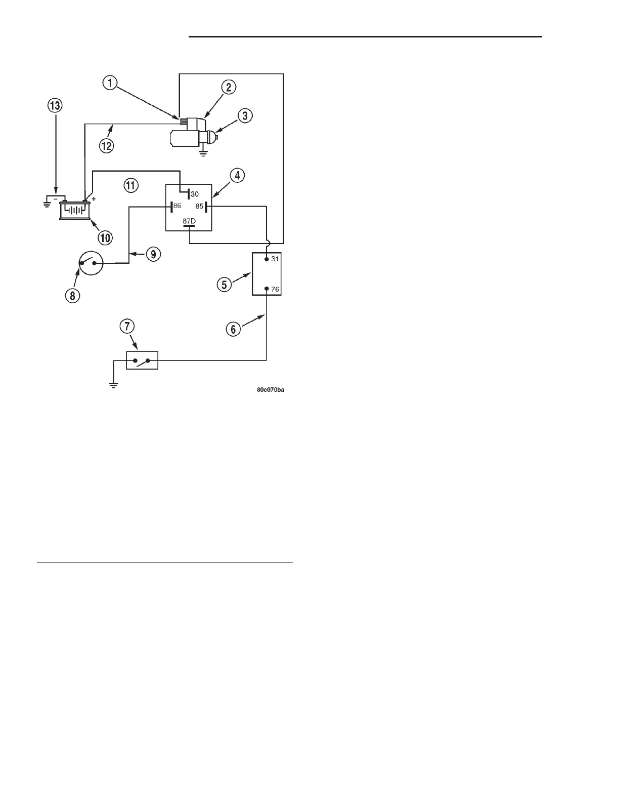
Fig. 1 Starting System Schematic
1 – SOLENOID TERMINAL
2 – STARTER SOLENOID
3 – STARTER MOTOR
4 – STARTER RELAY CONNECTOR
5 – PCM
6 – GROUND CIRCUIT
7 – TRANSMISSION RANGE SENSOR/PARK/NEUTRAL SENSE
8 – IGNITION SWITCH
9 – IGNITION FEED
10 – BATTERY
11 – BATTERY RELAY FEED
12 – POSITIVE CABLE
13 – NEGATIVE CABLE
8B - 2 STARTING SYSTEMS LH
DESCRIPTION AND OPERATION (Continued)