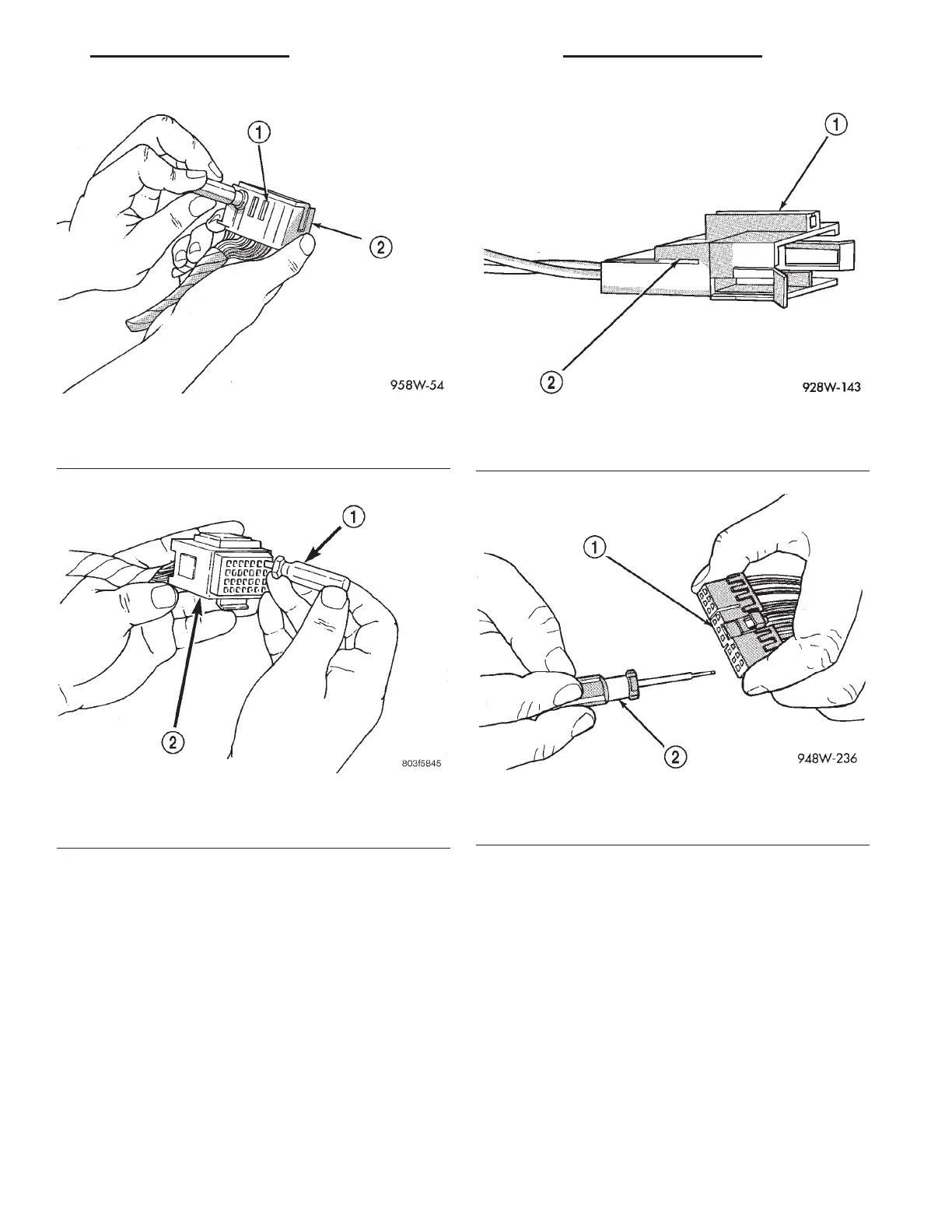
(4) Position the connector locking finger away from
the terminal using the proper pick from special tool
kit 6680. Pull on the wire to remove the terminal
from the connector (Fig. 17) (Fig. 18).
(5) Cut the wire 6 inches from the back of the con-
nector.
(6) Remove 1 inch of insulation from the wire on
the harness side.
(7) Select a wire from the terminal repair assem-
bly that best matches the color wire being repaired.
(8) Cut the repair wire to the proper length and
remove 1 inch of insulation.
(9) Place a piece of heat shrink tubing over one
side of the wire. Make sure the tubing will be long
enough to cover and seal the entire repair area.
(10) Spread the strands of the wire apart on each
part of the exposed wires.
(11) Push the two ends of wire together until the
strands of wire are close to the insulation.
(12) Twist the wires together.
(13) Solder the connection together using rosin
core type solder only. Do not use acid core solder.
(14) Center the heat shrink tubing over the joint
and heat using a heat gun. Heat the joint until the
tubing is tightly sealed and sealant comes out of both
ends of the tubing.
(15) Insert the repaired wire into the connector.
(16) Install the connector locking wedge, if
required, and reconnect the connector to its mating
half/component.
Fig. 14 Augat Connector Repair
1 – LOCKING TAB
2 – CONNECTOR
Fig. 15 Using Special Tool 6932
1 – SPECIAL TOOL 6932
2 – CONNECTOR
Fig. 16 Connector Locking Wedge Tab (Typical)
1 – CONNECTOR
2 – CONNECTOR LOCKING WEDGE TAB
Fig. 17 Terminal Removal
1 – CONNECTOR
2 – FROM SPECIAL TOOL KIT 6680
LH 8W - 01 GENERAL INFORMATION 8W - 01 - 13
SERVICE PROCEDURES (Continued)