In an Open Position: this will result in a noisy
compressor or no cooling. The cause can be a broken
spring, broken ball or excessive moisture in the A/C
system. If the spring or ball are found to be defective,
replace the expansion valve. If excessive moisture is
found in the A/C system, recycle the refrigerant.
In a Closed Position: There will be low suction
pressure and no cooling. This may be caused by a
failed power dome or excessive moisture in the A/C
system. If the power dome on the expansion valve is
found to be defective replace the expansion valve. If
excessive moisture is found recycle the refrigerant.
A Restricted Orifice: There will be low suction
pressure and no cooling. This may be caused by
debris in the refrigerant system. If debris is believed
to be the cause, recycle the refrigerant and replace
the expansion valve and filter/drier.
SELF DIAGNOSTICS
DIAGNOSTIC TROUBLE CODES (DTC’s)
Both the ATC and the Manual A/C system are con-
trolled by the Body Control Module (BCM). Both sys-
tems can be diagnosed by the DRBIIIt scan tool or
the vehicles own control head display. Refer to the
DRBIIIt menu for checking Diagnostic Trouble Codes
(DTC’s) Note that there are three DTC tables. The
ATC and Manual A/C DTC table contain faults that
are common to both the ATC and the Manual A/C
system. The same diagnosis can be used for both sys-
tems. The DTC’s cover operation of the climate con-
trol unit actuators, doors, evaporator temperature
sensor, ambient temperature sensor and the A/C
refrigerant system. The Manual A/C DTC table cov-
ers Fault Codes that are for the manual A/C Control
Head and wiring and are not used on an ATC sys-
tem. The ATC DTC table has DTC’s for ATC Head
Communications, In-Car Temperature Sensor and
Sun Sensor which are not in a Manual A/C system.
TROUBLE CODES FROM THE ATC CONTROL
The trouble codes can be checked with the ATC
control if a DRBIIIt scan tool is not available. The
control head can only be placed into the diagnostic
mode while the engine is running and the vehicle is
not moving. Set the control to a 75° F setting (so
there is no confusion with the 23-51 Diagnostic Trou-
ble Codes (DTC’s).
To place the system into it’s diagnostic mode, press
and hold the Floor, Mix and Defrost buttons (at the
same time). The ATC head display will begin to
blink. Release the Floor, Mix and Defrost buttons.
Once the control head enters the diagnostic mode,
the display on the control head will continue to blink.
This occurs until it completes its tests and climate
control unit door/actuator calibrations. Then it will
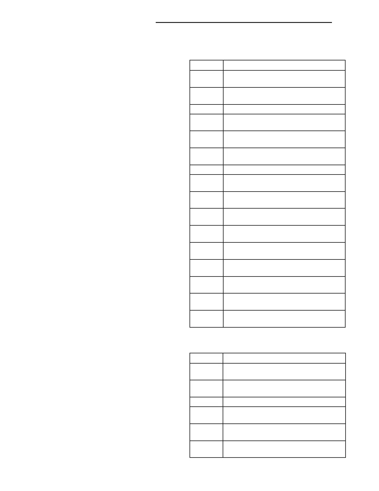
ATC AND MANUAL A/C DTC’S
CODE DESCRIPTION
23 BLEND DOOR ACTUATOR FEEDBACK
FAILURE
24 MODE DOOR ACTUATOR FEEDBACK
FAILURE
25 AMBIENT SENSOR
31 RECIRCULATION DOOR ACTUATOR
STALL FAILURE
32 BLEND DOOR ACTUATOR STALL
FAILURE
33 MODE DOOR ACTUATOR STALL
FAILURE
35 EVAPORATOR SENSOR FAILURE
37 BLEND DOOR ACTUATOR OUTPUT
SHORTED TO BATTERY
38 BLEND DOOR ACTUATOR OUTPUT
SHORTED TO GROUND
39 MODE DOOR ACTUATOR OUTPUT
SHORTED TO BATTERY
40 MODE DOOR ACTUATOR OUTPUT
SHORTED TO GROUND
41 RECIRC DOOR ACTUATOR OUPUT
SHORTED TO BATTERY
42 RECIRC DOOR ACTUATOR OUTPUT
SHORTED TO GROUND
43 COMMON DOOR OUTPUT SHORTED
TO BATTERY
44 COMMON DOOR OUTPUT SHORTED
TO GROUND
51 SYSTEM VOLTAGE TOO LOW FOR
DOOR CALIBRATION
MANUAL A/C DTC’S
CODE DESCRIPTION
45 A/C CONTROL BLEND DOOR INPUT
OPEN OR SHORTED TO GROUND
46 A/C CONTROL BLEND DOOR
SHORTED TO BATTERY
47 A/C CONTROL - A/C SWITCH FAILURE
48 A/C CONTROL MODE DOOR INPUT
SHORTED TO GROUND
49 A/C CONTROL MODE DOOR INPUT
SHORTED TO BATTERY
50 A/C CONTROL ELECTRIC BACKLITE
(EBL) SWITCH FAILURE
24 - 8 HEATING AND AIR CONDITIONING LH
DIAGNOSIS AND TESTING (Continued)