MEMORY HEATED SEAT/MIRROR MODULE
(MHSMM)
DESCRIPTION
The Memory Heated Seat and Mirror Module con-
trols the seat heaters, and is mounted unto the bot-
tom of the driver seat
OPERATION
The module controls the seat heaters and is con-
nected to the seat harness by four connectors. There
is only one module per memory and heated system.
The module cannot be repaired, and if faulty or dam-
aged will have to be replaced.
HEATED SEAT ELEMENT AND SENSOR
DESCRIPTION
Two heated seat elements are used in both of the
front seats, one for the seat cushion and the other for
the seat back. The two elements for each seat are
connected in series to the Memory Heated Seat/Mir-
ror Module (MHSMM).
The temperature sensor is a Negative Temperature
Coefficient (NTC) thermistor. One temperature sen-
sor is used for each set, and it is integrated into the
seat cushion heating element
OPERATION
The heating elements are sewn into the seat cush-
ion cover and seat back cover assemblies, which are
serviced individually. The heating elements and tem-
perature sensor cannot be repaired, and if faulty or
damaged, the affected seat cover must be replaced.
Refer to Group 23 Body, for the Seat Cushion Cover
and Seat Back Cover Removal and Installation.
DIAGNOSIS AND TESTING
HEATED SEAT SYSTEM
For circuit descriptions and diagrams, refer to
Group 8W, Wiring Diagrams.
Before testing the individual components in the
heated seat system, cheek the following:
• If the heated seat switch LED doesn’t light up
with the ignition in the ON position, and the switch
in the LO or HI position, check the battery voltage, If
the battery is below 10 volts, recharge the battery. If
the problem persists, then check the fuse in the junc-
tion block. If the fuse is OK, test the heated seat
switch as described in this group. If not OK, repair
the shorted circuit or component failure and replace
the faulty fuse.
• If the heated seat LED’s light up, but the heat-
ing elements don’t heat, check the circuit breaker in
the junction block. If the circuit is OK, test the
heated set elements as described in this group, oth-
erwise replace the faulty circuit breaker.
• Using a DRB IIIt scan tool, check DTC’s and
refer to the proper Body Diagnostic Procedures Man-
ual.
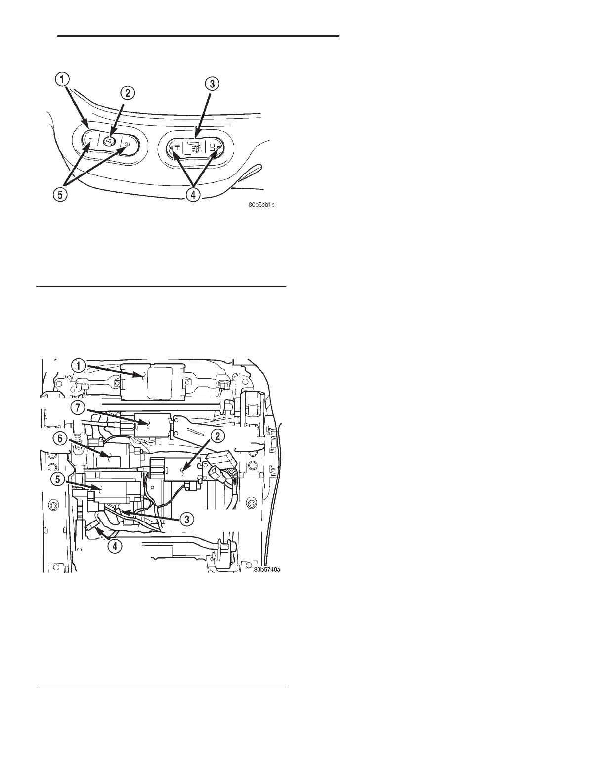
Fig. 2 Memory and Heated Seat Switches
1 – MEMORY SELECTOR SWITCH
2 – DRIVER POSITION SET
3 – HEATED SEAT SWITCH
4 – LED’S
5 – DRIVER POSITION
Fig. 3 Memory Heated Seat/Mirror Module (MHSMM)
Location
1 – MHSMM
2 – RECLINER MOTOR
3 – SEAT HEATER 4–WAY CONNECTOR
4 – SEAT BACK HEATER 2–WAY CONNECTOR
5 – REAR RISER
6 – FRONT RISER
7 – HORIZONTAL MOTOR
LH ELECTRICALLY HEATED SYSTEMS 8N - 7
DESCRIPTION AND OPERATION (Continued)