BODY CONTROL MODULE (BCM)
REMOVAL
(1) With the Junction Block/BCM removed from
the vehicle, refer to Group 8O, Power Distribution
Systems for Removal and Installation.
(2) Remove the four BCM attaching screws from
the Junction Block.
(3) Disconnect BCM from the Junction Block.
NOTE: The Remote Keyless Entry (RKE) module is
attached to the BCM with three screws. This must
be transferred (if equipped) to the new BCM.
NOTE: If the BCM is replaced, the Vehicle Theft /
Security System (VTSS (if equipped) must be
enabled in the new BCM via the DRB lllT in order to
start the vehicle.
INSTALLATION
For installation, reverse the above procedures.
Ensure that the wire terminals and connectors are
in good condition and connectors are properly
installed when reinstalling Junction Block / BCM.
BRAKE LAMP/SPEED CONTROL CUTOUT
SWITCH
REMOVAL
(1) Open hood and disconnect the negative battery
cable remote terminal from the remote battery post
(Fig. 22).
(2) Remove the left under instrument panel silenc-
er/duct.
(3) Twist and pull the switch assembly rearward
from the brake bracket. After switch is free discon-
nect the wire connector and remove switch.
INSTALLATION
For installation, reverse the above procedures.
CIGAR LIGHTER/POWER OUTLET ASSEMBLY
REMOVAL
(1) Open hood and disconnect the negative battery
cable remote terminal from the remote battery post
(Fig. 22).
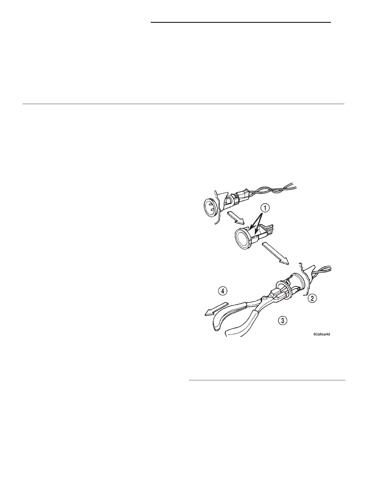
(2) Look inside and note position of the retaining
bosses (Fig. 11).
(3) Using external snap ring pliers with 90 degree
tips. Insert pliers with tips against bosses and
squeeze forcing bosses out of base.
(4) Pull out the base through mounting ring by
gently rocking pliers. A tool can be made to do the
same. Refer to (Fig. 12).
(5) Disconnect the base wires.
(6) Set base aside and remove base mount ring.
1 – BEZEL, INSTRUMENT PANEL END CAP
2 – COVER, UPPER INSTRUMENT PANEL
3 – LOUVER, AIR OUTLET
4 – LOUVER/DEMISTER SIDE WINDOW
5 – MODULE, PASSENGER SIDE AIRBAG
6 – BEZEL, INSTRUMENT PANEL END CAP
7 – GLOVE BOX ASSEMBLY, INSTRUMENT PANEL
8 – BEZEL, INSTRUMENT PANEL UPPER RIGHT TRIM
9 – BEZEL, INSTRUMENT PANEL TRIM-CENTER
10 – BEZEL, INSTRUMENT PANEL AIR DISTRIBUTION OUTLET
11 – BEZEL, INSTRUMENT CLUSTER
12 – STORAGE COMPARTMENT CUBBY BOX
13 – LEVER, PARKING BRAKE
14 – COVER, LOWER INSTRUMENT PANEL-LEFT SIDE
15 – INSTRUMENT PANEL ASSEMBLY
Fig. 11 Cigar Lighter / Power Outlet Base Removal
1 – RETAINING BOSSES-ENGAGE PLIERS HERE
2 – PARTIALLY REMOVED
3 – EXTERNAL SNAP-RING PLIERS
4 – PULL BASE OUT-THROUGH MOUNTING RING
8E - 10 INSTRUMENT PANEL SYSTEMS LH
REMOVAL AND INSTALLATION (Continued)