Two different ICU’s (HCU and CAB) are used on
this vehicle depending on whether or not the vehicle
is equipped with traction control. The HCU on a
vehicle equipped with traction control has a valve
block that is approximately one inch longer than a
HCU on a vehicle that is equipped with ABS only.
The ABS-only ICU consists of the following compo-
nents: the CAB, eight (build/decay) solenoid valves
(four inlet valves and four outlet valves), valve block,
fluid accumulators, a pump, and an electric motor.
The ABS-with traction control ICU consists of the
following components: the CAB, eight (build/decay)
solenoid valves (four inlet valves and four outlet
valves), two traction control (ASR) valves, two
hydraulic shuttle valves, valve block, fluid accumula-
tors, a pump, and an electric motor.
The replaceable components of the ICU are the
HCU and the CAB. No attempt should be made to
service any individual components of the HCU or
CAB.
OPERATION
For information of the ICU, refer to these individ-
ual components of the ICU:
• CONTROLLER ANTILOCK BRAKE (CAB)
• HYDRAULIC CONTROL UNIT (HCU)
For information on the ICU’s hydraulic circuits,
refer to HYDRAULIC CIRCUITS AND VALVE
OPERATION which can be found elsewhere in this
section.
CONTROLLER ANTILOCK BRAKE (CAB)
DESCRIPTION
The controller antilock brake (CAB) is a micropro-
cessor-based device which monitors the ABS system
during normal braking and controls it when the vehi-
cle is in an ABS stop. The CAB is mounted to the
bottom of the HCU (Fig. 1). The CAB uses a 25-way
electrical connector on the vehicle wiring harness.
The power source for the CAB is through the ignition
switch in the RUN or ON position. The CAB is on
the PCI bus.
OPERATION
The primary functions of the CAB are to:
• Monitor the antilock brake system for proper
operation.
• Detect wheel locking or wheel slipping tenden-
cies by monitoring the speed of all four wheels of the
vehicle.
• Control fluid modulation to the wheel brakes
while the system is in an ABS mode.
• Store diagnostic information.
• Provide communication to the DRB scan tool
while in diagnostic mode.
• Illuminate the amber ABS warning lamp.
• (with traction control only) Illuminate the TRAC
ON lamp in the message center on the instrument
panel when a traction control event occurs.
• (with traction control only) Illuminate the TRAC
OFF lamp when the amber ABS warning lamp illu-
minates.
The CAB constantly monitors the antilock brake
system for proper operation. If the CAB detects a
fault, it will turn on the amber ABS warning lamp
and disable the antilock braking system. The normal
base braking system will remain operational.
NOTE: If the vehicle is equipped with traction con-
trol, the TRAC OFF lamp will illuminate anytime the
amber ABS warning lamp illuminates.
The CAB continuously monitors the speed of each
wheel through the signals generated by the wheel
speed sensors to determine if any wheel is beginning
to lock. When a wheel locking tendency is detected,
the CAB commands the CAB command coils to actu-
ate. The coils then open and close the valves in the
HCU that modulate brake fluid pressure in some or
all of the hydraulic circuits. The CAB continues to
control pressure in individual hydraulic circuits until
a locking tendency is no longer present.
The CAB contains a self-diagnostic program that
monitors the antilock brake system for system faults.
When a fault is detected, the amber ABS warning
lamp is turned on and the fault diagnostic trouble
code (DTC) is then stored in a diagnostic program
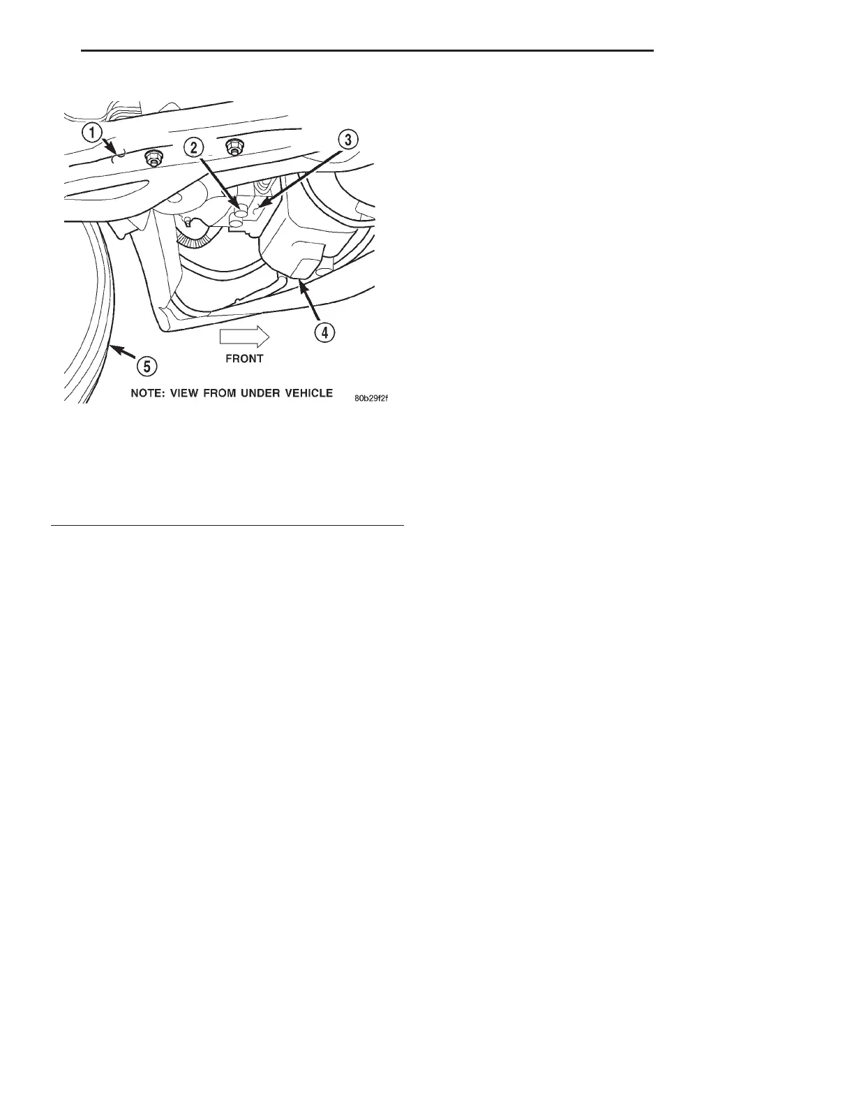
Fig. 2 Integrated Control Unit (HCU And CAB)
Location
1 – ENGINE CRADLE
2 – HCU
3 – CONTROLLER ANTILOCK BRAKE (CAB)
4 – BOTTOM OF WINDSHIELD WASHER RESERVOIR
5 – LEFT FRONT TIRE
LH BRAKES 5 - 57
DESCRIPTION AND OPERATION (Continued)