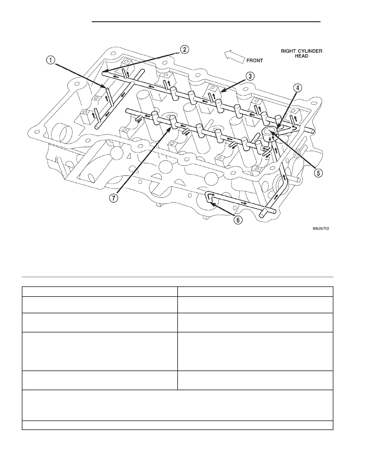
Fig. 13 Cylinder Head Oil Lubrication System—Right Side
1 – OIL FEED TO CAMSHAFT (SECONDARY) CHAIN
TENSIONER
2 – OIL FEED TO TIMING CHAIN (PRIMARY) TENSIONER
3 – CAM JOURNALS
4 – ACCUMULATOR
5 – VENT HOLE
6 – OIL FEED FROM BLOCK
7 – LASH ADJUSTOR BORES
FROM: TO:
Right Cylinder Head Oil Inlet Gallery (intake side of
head)
Oil Gallery and Accumulator – Rear of Head*
Oil Gallery and Accumulator – Rear of Head* 1. Exhaust Camshaft Oil Passage
2. Intake Camshaft Oil Passage
Right Exhaust Camshaft Oil Passage 1. Right Exhaust Camshaft Journals
2. Hydraulic Valve Lash Adjusters and Rocker Arms
3. Right Camshaft (Secondary) Chain Tensioner
4. Primary Timing Chain Tensioner - Right Head**
Right Intake Camshaft Oil Passage 1. Right Intake Camshaft Journals
2. Hydraulic Valve Lash Adjusters and Rocker Arms
* When oil reaches the back of the cylinder head, the oil gallery feeds oil into an accumulator chamber that is
located towards center of the head. The accumulator chamber is closed off with a pressed in core plug that has a
small orifice to act as a vent. Oil then travels down at a 45 degree angle from the accumulator into two passages,
one for the intake and one for the exhaust side of the cylinder head.
** The timing (primary) chain tensioner is the last component to receive oil on the right cylinder head.
9 - 12 2.7L ENGINE LH
DESCRIPTION AND OPERATION (Continued)