POWER STEERING GEAR
TABLE OF CONTENTS
page page
DESCRIPTION AND OPERATION
POWER STEERING GEAR..................29
DIAGNOSIS AND TESTING
OUTER TIE ROD SOCKET END PLAY
MEASUREMENT........................30
REMOVAL AND INSTALLATION
SERVICE WARNINGS AND CAUTIONS ........31
POWER STEERING GEAR..................31
OUTER TIE ROD END .....................38
DISASSEMBLY AND ASSEMBLY
POWER STEERING GEAR HOUSING
BUSHING .............................40
SPECIFICATIONS
POWER STEERING GEAR FASTENER
TORQUE SPECIFICATIONS ...............40
SPECIAL TOOLS
POWER STEERING GEAR..................41
DESCRIPTION AND OPERATION
POWER STEERING GEAR
DESCRIPTION
This vehicle is equipped with a rack-and-pinion
power steering gear (Fig. 1). The gear is a center-
take-off type gear. Center-take-off means that the tie
rods are connected to the steering gear via a rack
guide located at the center of the gear.
The power steering gear is mounted on the cross-
member behind the engine. The steering column
intermediate shaft connects to the pinion shaft of the
gear. The outer ends of the outer tie rods attach to
steering arms on the suspension’s front struts.
Three different power steering gears are available:
a base gear, a firm feel gear, and a speed propor-
tional gear. The base gear and firm feel gear are ser-
viced the same and are covered in this section. The
speed proportional steering gear is physically very
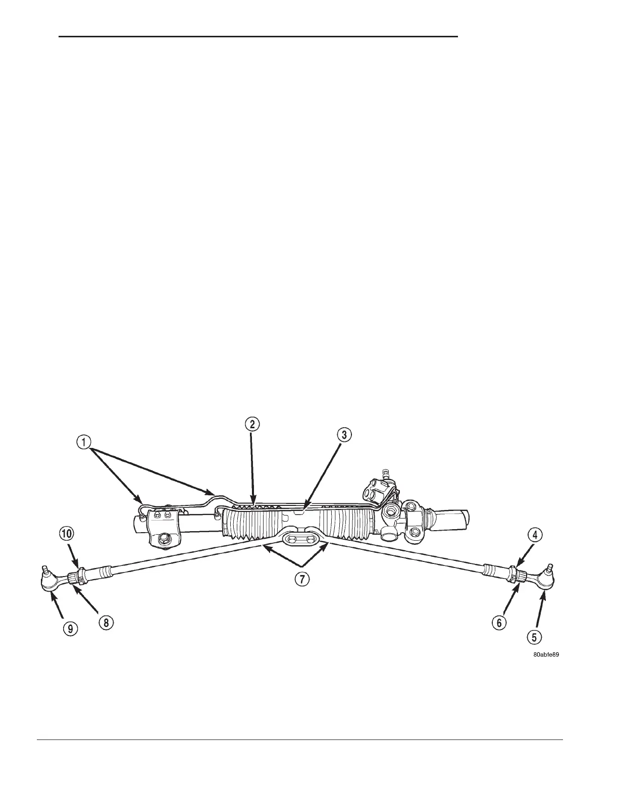
Fig. 1 Power Steering Gear
1 – STEERING GEAR FLUID LINES
2 – STEERING GEAR BOOT
3 – RACK AND PINION STEERING GEAR
4 – CLAMP
5 – TIE ROD END
6 – ADJUSTMENT SLEEVE
7 – INNER TIE ROD
8 – ADJUSTMENT SLEEVE
9 – TIE ROD END
10 – CLAMP
LH STEERING 19 - 29