(3) Remove plastic back panel from the seat back.
Refer to Group 23, Body for the procedure.
(4) Disengage seat back trim cover J-strap from
the upper, lower and airbag side of seat back.
(5) Disconnect the side airbag module electrical
connector. Slide yellow locking tab down to unlock.
Then with two fingers, push two side retaining tabs
in and pull connector straight from module.
(6) Remove the front seat cushion side shield.
Refer to Group 23, Body for the procedure.
(7) Disengage pushpin and remove the wire har-
ness (Fig. 23) from the seat assembly.
INSTALLATION
(1) Install airbag wire harness in seat. Be certain
wire harness routing is correct. Harness should fol-
low leading edge of seat back frame down into lower
seat cushion. Once inserted in lower cushion harness
is positioned between the cushion pan and seat track
and held in place with pushpin.
(2) Connect the side airbag module electrical con-
nector. After initial connector is installed be certain
the yellow locking tab is in the upper “locked” posi-
tion. Check to be certain connector cannot be
removed once yellow locking tab is positioned.
(3) Install seat back trim cover J-straps on the
upper, lower and airbag side of seat back frame.
CAUTION: ALWAYS INSTALL NEW PUSHPINS,
WHEN INSTALLING SEAT BACK PLASTIC BACK
COVER.
(4) Install the plastic back panel on the seat back.
Install new pushpins in the upper mounting location
of the back cover. Refer to Group 23, Body for the
procedure.
(5) Install the front seat cushion side shield. Refer
to Group 23, Body for the procedure.
CAUTION: BE CERTAIN PLASTIC BACK COVER IS
SECURELY INSTALLED ON THE SEAT BACK. FAIL-
URE TO DO SO WILL ADVERSELY AFFECT THE
AIRBAG SYSTEM.
(6) Install the left front seat in the vehicle. Refer
to Group 23, Body for the procedure.
(7) Connect the negative battery cable.
(8) Using the DRB III Scan Tool erase any stored
DTC’s and perform Airbag System Diagnostics.
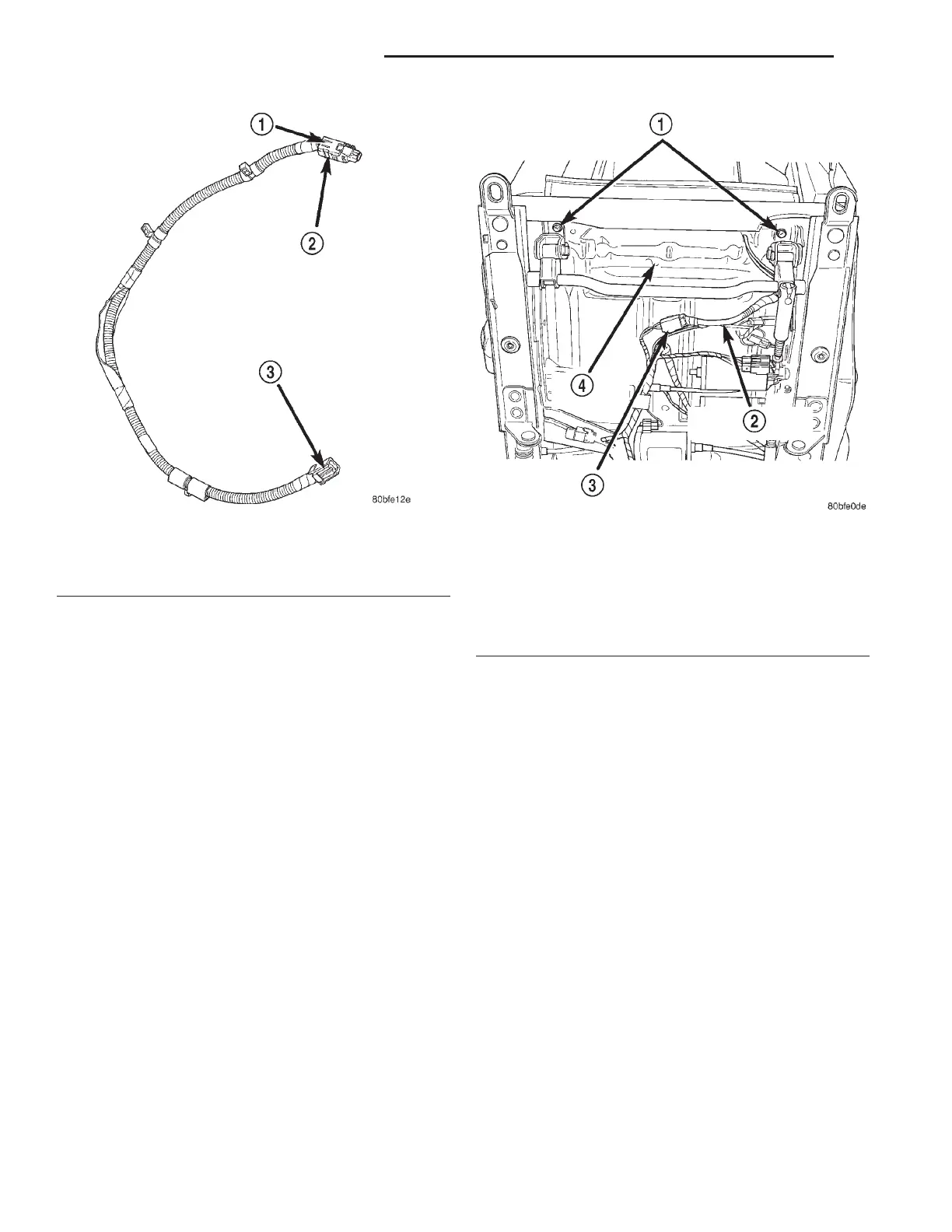
Fig. 22 Airbag Seat Wire Harness
1 – YELLOW CONNECTOR LOCK
2 – TO AIRBAG MODULE
3 – TO SEAT HARNESS
Fig. 23 Wire Harness Position & Orientation –
Passenger Seat Shown Here Driver Seat (Mirror
Image)
1 – SEAT TRACK RETAINING BOLTS
2 – SEAT AIRBAG WIRE HARNESS
3 – SEAT AIRBAG WIRE HARNESS CONNECTOR
4 – CUSHION PAN
8M - 18 PASSIVE RESTRAINT SYSTEMS LH
REMOVAL AND INSTALLATION (Continued)
2000 LHS, 300M, CONCORDE AND INTREPID