TENSION STRUT
To replace the tension strut, the tension strut and
lower control arm first MUST be removed as an
assembly from the vehicle.
DISASSEMBLY
(1) Raise vehicle using a frame contact type hoist
or supported as required using jack stands. See
Hoisting in the Lubrication and Maintenance group
of this service manual for the required hoisting or
jacking procedure to be used for this vehicle.
(2) Remove the wheel and tire from the car.
(3) Remove lower control arm and tension strut as
an assembly from the vehicle. See Lower Control
Arm Removal in this section of the service manual
for the required removal procedure.
(4) Separate the tension strut from the lower con-
trol arm assembly.
(5) Inspect tension strut bushing in lower control
arm for excessive wear or deterioration. If tension
strut bushing is found to be defective replace lower
control tension strut bushing at this time. Refer to
Lower Control Arm Bushing Service in this section of
the service for tension strut removal and installation
procedure.
ASSEMBLY
(1) Position tension strut in lower control as shown
in (Fig. 75), with word FRONT stamped in tension
strut positioned away from control arm (Fig. 75).
With an open end wrench on flat of tension strut to
keep tension strut from turning. Tighten NEW ten-
sion strut to lower control retaining nut to a torque
of 130 N·m (95 ft. lbs.).
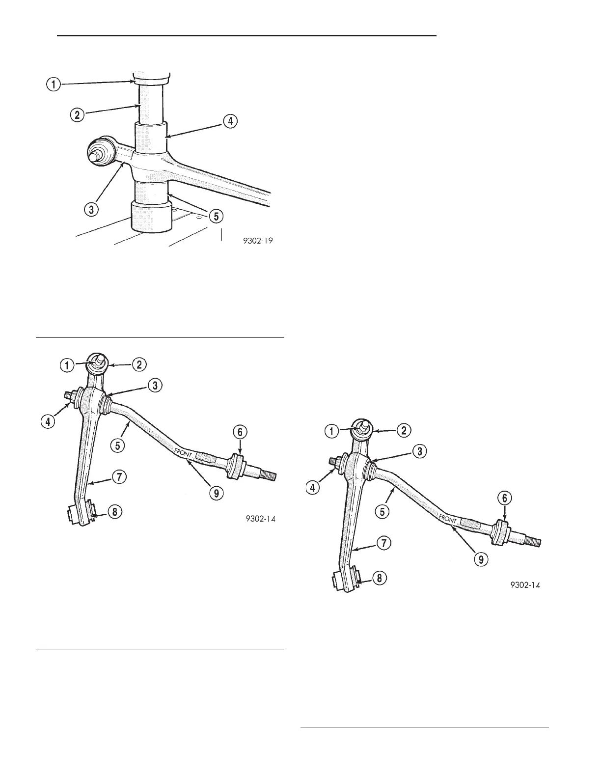
Fig. 73 Installing Tension Strut Bushing Into Lower
Control Arm
1 – ARBOR PRESS
2 – SPECIAL TOOL 6644-2
3 – LOWER CONTROL ARM
4 – SPECIAL TOOL 6644-3
5 – SPECIAL TOOL MB990799
Fig. 74 Tension Strut Installed In Lower Control Arm
1 – BALL JOINT STUD
2 – BALL JOINT SEAL
3 – LOWER CONTROL ARM TENSION STRUT BUSHING
4 – NUT
5 – TENSION STRUT
6 – TENSION STRUT TO CRADLE ISOLATOR BUSHING
7 – LOWER CONTROL ARM
8 – LOWER CONTROL ARM PIVOT BUSHING
9 – WORD “FRONT” STAMPED IN CONTROL ARM HERE
Fig. 75 Tension Strut Installed In Lower Control
Arm.
1 – BALL JOINT STUD
2 – BALL JOINT SEAL
3 – LOWER CONTROL ARM TENSION STRUT BUSHING
4 – NUT
5 – TENSION STRUT
6 – TENSION STRUT TO CRADLE ISOLATOR BUSHING
7 – LOWER CONTROL ARM
8 – LOWER CONTROL ARM PIVOT BUSHING
9 – WORD “FRONT” STAMPED IN CONTROL ARM HERE
LH SUSPENSION 2 - 39
DISASSEMBLY AND ASSEMBLY (Continued)