memory. These DTC’s will remain in the CAB mem-
ory even after the ignition has been turned off. The
DTC’s can be read and cleared from the CAB mem-
ory by a technician using the DRB scan tool. If not
cleared with a DRB scan tool, the fault occurrence
and DTC will be automatically cleared from the CAB
memory after the identical fault has not been seen
during the next 3,500 miles.
CONTROLLER ANTILOCK BRAKE INPUTS
• wheel speed sensors (four)
• brake lamp switch
• ignition switch
• system and pump voltage
• ground
• traction control switch (if equipped)
• diagnostic communication (PCI)
CONTROLLER ANTILOCK BRAKE OUTPUTS
• amber ABS warning lamp actuation (via BUS)
• instrument cluster (MIC) communication (PCI)
• traction control lamps (if equipped)
• diagnostic communication (PCI, via BUS)
HYDRAULIC CONTROL UNIT (HCU)
DESCRIPTION
The hydraulic control unit (HCU) is mounted to
the CAB as part of the ICU (Fig. 3). The ICU is
located in front of the driver’s side front tire, behind
the inner fender splash shield. The HCU controls the
flow of brake fluid to the brakes using a series of
valves and accumulators. A pump/motor is mounted
on the HCU to supply build pressure to the brakes
during an ABS stop.
The HCU on a vehicle equipped with traction con-
trol has a valve block that is approximately one inch
longer than a HCU on a vehicle that is equipped
with ABS only in order to incorporate the additional
valves.
For more information, see INTEGRATED CON-
TROL UNIT in this section.
OPERATION
The operation of the HCU’s hydraulic circuits can
be found in HYDRAULIC CIRCUITS AND VALVE
OPERATION which can be found elsewhere in this
section.
The following topics explain how the different com-
ponents within the HCU operate.
VALVES AND SOLENOIDS
The valve block contains four inlet valves and four
outlet valves. The inlet valves are spring-loaded in
the open position and the outlet valves are spring-
loaded in the closed position during normal braking.
The fluid is allowed to flow from the master cylinder
to the wheel brakes.
During an ABS stop, these valves cycle to maintain
the proper slip ratio for each wheel. The inlet valve
closes preventing further pressure increase and the
outlet valve opens to provide a path from the wheel
brake to the HCU accumulators and pump/motor.
This releases (decays) pressure from the wheel brake,
thus releasing the wheel from excessive slippage.
Once the wheel is no longer slipping, the outlet valve
is closed and the inlet valve is opened to reapply
(build) pressure.
For information on the valves used with the trac-
tion control system, refer to TRACTION CONTROL
SYSTEM in this section.
BRAKE FLUID ACCUMULATORS
There are two fluid accumulators in the HCU–one
for the primary hydraulic circuit and one for the sec-
ondary hydraulic circuit (Fig. 3). Each hydraulic cir-
cuit usesa5ccaccumulator.
The fluid accumulators temporarily store brake
fluid that is removed from the wheel brakes during
an ABS cycle. This stored fluid is used by the pump/
motor to provide build pressure for the brake hydrau-
lic system. When the antilock stop is complete, the
accumulators are drained by the pump/motor.
PUMP/MOTOR
There are two pump assemblies in the HCU–one
for the primary hydraulic circuit and one for the sec-
ondary hydraulic circuit. Both pumps are driven by a
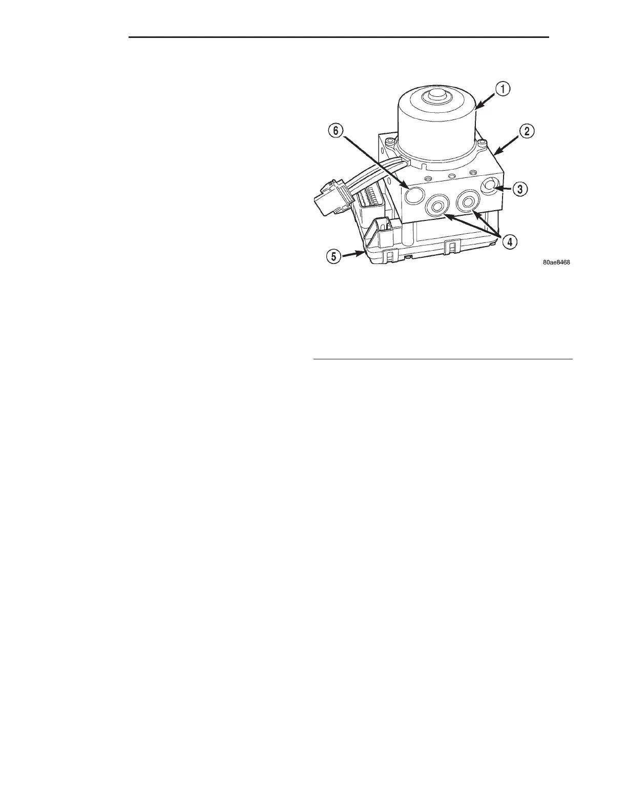
Fig. 3 Integrated Control Unit (ICU)
1 – PUMP MOTOR
2 – HYDRAULIC CONTROL UNIT (HCU)
3 – NOISE DAMPENING CHAMBER
4 – LOW PRESSURE FLUID ACCUMULATORS
5 – CAB
6 – LIP SEAL SAVER
5 - 58 BRAKES LH
DESCRIPTION AND OPERATION (Continued)