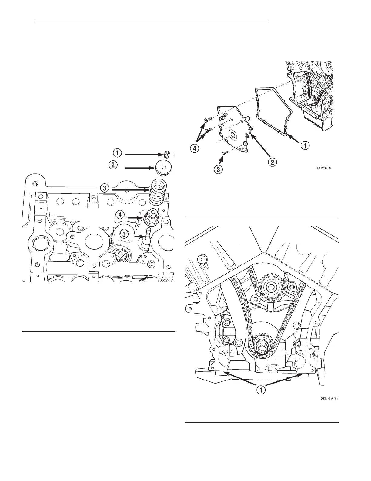
(3) Install valve seal/spring seat assembly over
valve guides on all valve stems (Fig. 66). Ensure that
the garter spring is intact around the top of the rub-
ber seal. Install valve springs, valve retainers.
(4) Compress valve springs with a valve spring
compressor install locks and release tool. If valves
and/or seats are reground, measure the
installed height of springs (B) (Fig. 65), make
sure measurements are taken from top of
spring seat to the bottom surface of spring
retainer. If height is greater than 38.75 mm (1.5256
inches), install a 0.762 mm (0.030 inch.) spacer in
head counterbore under the valve spring seat to
bring spring height back within specification.
TIMING CHAIN COVER
REMOVAL
(1) Disconnect negative cable from remote jumper
terminal.
(2) Remove upper radiator support crossmember.
Refer to BODY for procedure.
(3) Remove fan module and accessory drive belts.
Refer to COOLING SYSTEM for procedure.
(4) Remove crankshaft damper. Refer to procedure
in this section.
(5) Remove power steering pump from mounting
bracket.
(6) Remove accessory drive belt tensioner pulley
and bracket.
(7) Remove timing chain cover attaching bolts and
remove cover (Fig. 67).
INSTALLATION
(1) Inspect and clean sealing surfaces. Inspect and
replace gasket and seal as necessary.
Fig. 66 Valve, Spring, and Valve Stem Seal
1 – VALVE RETAINING LOCKS
2 – VALVE SPRING RETAINER
3 – VALVE SPRING
4 – VALVE SEAL AND VALVE SPRING SEAT ASSEMBLY
5 – VALVE
Fig. 67 Timing Chain Cover
1 – GASKET
2 – TIMING CHAIN COVER
3 – BOLT-M6
4 – BOLT-M10
Fig. 68 Timing Chain Cover Sealing
1 – PLACE A 1/8 INCH BEAD OF SEALER AT PARTING LINE
LH 2.7L ENGINE 9 - 45
REMOVAL AND INSTALLATION (Continued)