(1) Slide inner tripod joint seal boot retaining
clamp, onto interconnecting shaft. Then slide replace-
ment inner tripod joint sealing boot onto the inter-
connecting shaft. Inner tripod joint seal boot
MUST be positioned on interconnecting shaft,
so only the thinnest (sight) groove on intercon-
necting shaft is visible (Fig. 26).
(2) Install the spider assembly onto the intercon-
necting shaft. Spider assembly must be installed on
interconnecting shaft far enough to fully install the
retaining snap ring. If spider assembly will not fully
install on interconnecting shaft by hand, it can be
installed by tapping the spider body with a brass
drift. Do not hit the outer tripod bearings in an
attempt to install spider assembly on intercon-
necting shaft.
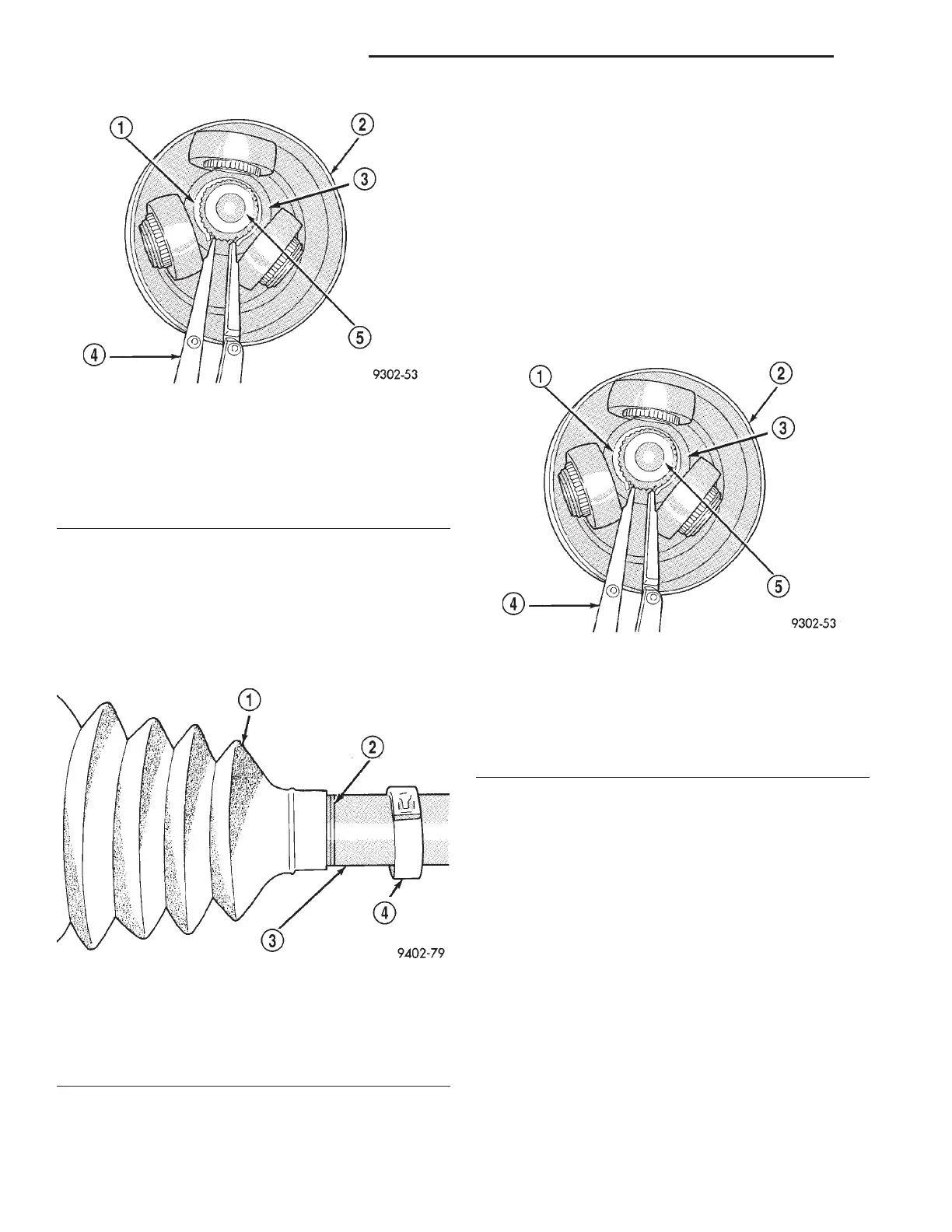
(3) Install the spider assembly to interconnecting
shaft retaining snap ring into groove on end of inter-
connecting shaft (Fig. 27). Verify the snap ring is
fully seated into groove on interconnecting shaft.
(4) Distribute 1/2 the amount of grease provided in
the seal boot service package (DO NOT USE ANY
OTHER TYPE OF GREASE) into tripod housing. Put
the remaining amount into the sealing boot.
(5) Slide the spider assembly and the interconnect-
ing shaft into the tripod joint housing (Fig. 28).
(6) Install inner tripod joint seal boot to intercon-
necting shaft clamp evenly on sealing boot.
(7) Clamp sealing boot onto interconnecting shaft
using Crimper, Special Tool C-4975 and the following
procedure. Place crimping tool C-4975 over bridge of
clamp (Fig. 29). Tighten nut on crimping tool C-4975
until jaws on tool are closed completely together, face
to face (Fig. 30).
CAUTION: Seal must not be dimpled, stretched or
out of shape in any way. If seal is NOT shaped cor-
rectly, equalize pressure in seal and shape it by
hand.
Fig. 25 Spider Assembly Retaining Snap Ring
Removal
1 – SNAP RING
2 – SEALING BOOT
3 – SPIDER ASSEMBLY
4 – SNAP RING PLIERS
5 – INTERCONNECTING SHAFT
Fig. 26 Seal Boot Correctly Positioned On
Interconnecting Shaft
1 – SEALING BOOT
2 – INTERCONNECTING SHAFT THINNEST GROOVE
3 – INTERCONNECTING SHAFT
4 – BOOT CLAMP
Fig. 27 Spider Assembly Retaining Snap Ring
Installation
1 – SNAP RING
2 – SEALING BOOT
3 – SPIDER ASSEMBLY
4 – SNAP RING PLIERS
5 – INTERCONNECTING SHAFT
3 - 12 DIFFERENTIAL AND DRIVELINE LH
DISASSEMBLY AND ASSEMBLY (Continued)