CAUTION: When inserting center punch into rear
spindle, use care so point of center punch does not
puncture strut assembly.
(14) Insert a center punch into the hole on the
spindle (Fig. 9). Center punch must be tapped into
spindle until jammed into hole. This will spread spin-
dle casting allowing it to be removed from strut
assembly.
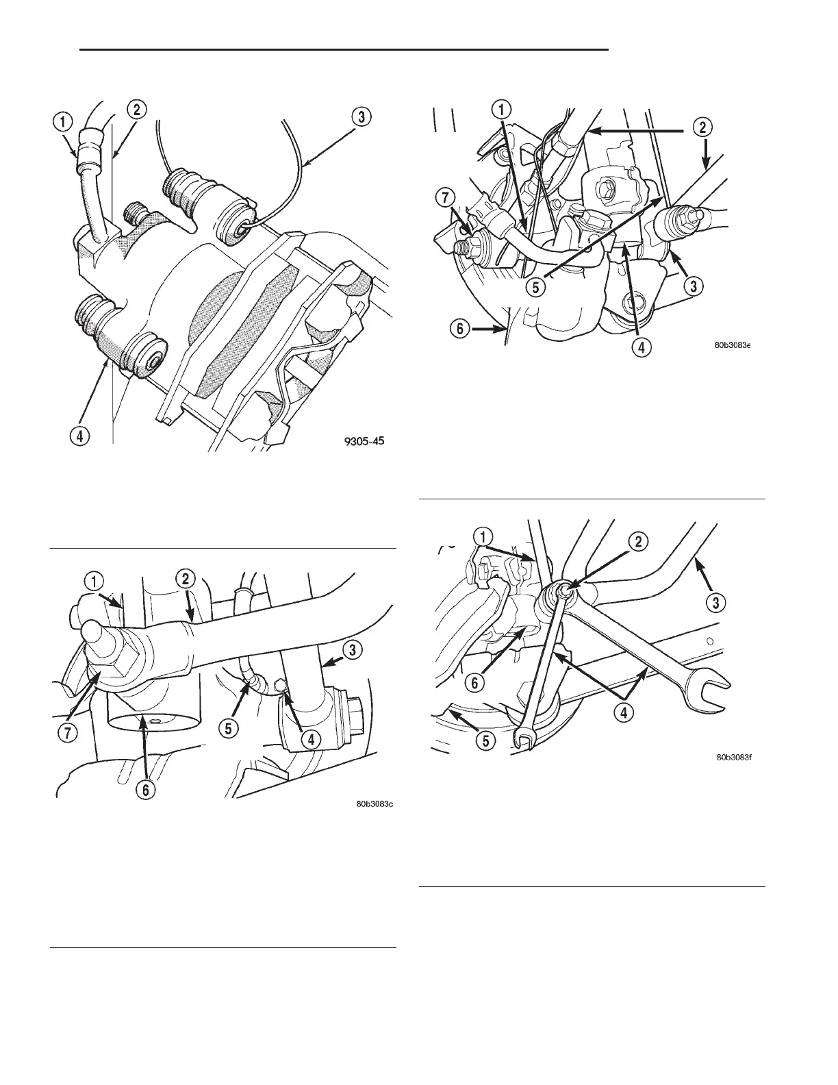
Fig. 4 Storing Rear Caliper Assembly
1 – FLEX HOSE
2 – STRUT
3 – WIRE HANGER
4 – CALIPER ASSEMBLY
Fig. 5 Wheel Speed Sensor At Adapter
1 – STABILIZER BAR LINK
2 – STABILIZER BAR
3 – LATERAL LINK
4 – BOLT
5 – WHEEL SPEED SENSOR
6 – STRUT ASSEMBLY
7 – NUT
Fig. 6 Lateral Links To Spindle Attachment
1 – SPINDLE
2 – LATERAL LINKS
3 – LATERAL LINK ATTACHING BOLT HEAD
4 – STRUT ASSEMBLY
5 – STABILIZER BAR ATTACHING LINK
6 – BRAKE CALIPER
7 – LATERAL LINK ATTACHING BOLT NUT
Fig. 7 Link Attachment To Stabilizer Bar
1 – STABILIZER BAR ATTACHING LINK
2 – LINK STUD
3 – STABILIZER BAR
4 – WRENCHES
5 – BRAKE CALIPER
6 – STRUT ASSEMBLY
LH SUSPENSION 2 - 49
REMOVAL AND INSTALLATION (Continued)