CAUTION: Before installing the upper mount, make
sure the correct upper mount is being installed on
the strut. DO NOT install a right mount on a left
front strut or a left mount on a right front strut.
Incorrect mount installation may cause poor vehicle
ride and steering feel, and excessive front end
noise. A lead or drift condition may also be the
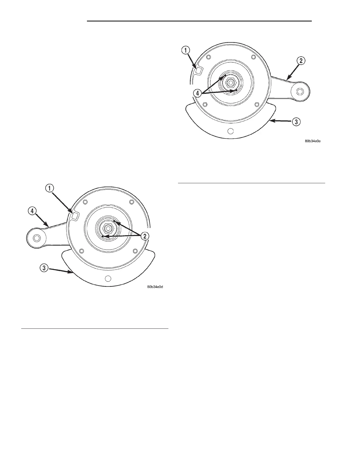
result. Left and right mounts look similar, but are
different from one another. Looking down at the top
of the upper mount, 2 tabs can be seen, (Fig. 66)
and (Fig. 67), down inside the mount center well. A
rectangular hole can be seen on the edge of the
mount mounting surface (Fig. 66) and (Fig. 67). This
is always in the 10 o’clock position when observing
rubber tab positioning, whether a left or right mount
is being observed. Once this hole is located in the
10 o’clock position, the tabs should be in the posi-
tions as shown (Fig. 66) and (Fig. 67). The right
upper mount should also have a white dot painted
on its mounting face.
(8) Install the strut upper mount over the strut
shaft and onto the top of the seat and bearing.
Loosely install the retaining nut on the strut shaft.
(9) Install Strut Nut Socket (on the end of a torque
wrench), Special Tool 6864, on the strut shaft retain-
ing nut (Fig. 63). Next, install a socket on the hex on
the end of the strut shaft. While holding the strut
shaft from turning, tighten the strut shaft retaining
nut to a torque of 94 N·m (70 ft. lbs.).
(10) Slowly release the tension from the coil spring
by backing off the compressor drive fully. As the ten-
sion is relieved, make sure the upper mount and seat
and bearing align properly. Verify the upper mount
does not bind.
(11) Remove the clamp from the lower end of the
coil spring and strut. Push back the spring compres-
sor upper and lower hooks, then remove the strut
assembly from the spring compressor.
(12) Install the strut assembly on the vehicle.
Refer to REMOVAL AND INSTALLATION in this
section for the required procedure.
LOWER CONTROL ARM PIVOT BUSHING
To replacement the lower control arm pivot bush-
ing, the control arm and tension strut assembly must
be removed from the vehicle. The removal and
replacement of the lower control arm pivot bushing
must be performed using an arbor press.
DISASSEMBLY
(1) Raise vehicle using a frame contact type hoist
or supported as required using jackstands. See Hoist-
ing in the Lubrication and Maintenance group of this
service manual for the required hoisting procedure to
be used for this vehicle.
(2) Remove lower control arm and tension strut as
an assembly from the vehicle. See Lower Control
Arm Removal in this section of the service manual
for the required removal procedure.
(3) Separate the tension strut from the lower con-
trol arm assembly.
(4) Position lower control arm in arbor press with
large end of pivot bushing inside Receiver, Special
Tool MB-990799, and special tool supporting lower
control arm (Fig. 68). Position Remover, Special Tool,
6644-2 on top of pivot bushing (Fig. 68). Using the
arbor press, press the lower control arm pivot bush-
ing out of lower control arm.
Fig. 66 Left Front Strut Upper Mount
1 – NOTCH
2 – RUBBER TABS
3 – OUTBOARD STRUT COIL SPRING SEAT
4 – STEERING ARM
Fig. 67 Right Front Strut Upper Mount
1 – NOTCH
2 – STEERING ARM
3 – OUTBOARD STRUT COIL SPRING SEAT
4 – RUBBER TABS
2 - 36 SUSPENSION LH
DISASSEMBLY AND ASSEMBLY (Continued)