CYLINDER BORE—HONING
(1) Used carefully, the cylinder bore resizing hone,
recommended tool C-823 or equivalent, equipped
with 220 grit stones, is the best tool for this honing
procedure. In addition to deglazing, it will reduce
taper and out-of-round as well as removing light
scuffing, scoring or scratches. Usually a few strokes
will clean up a bore and maintain the required lim-
its.
(2) Deglazing of the cylinder walls may be done
using a cylinder surfacing hone, recommended tool
C-3501 or equivalent, equipped with 280 grit stones,
if the cylinder bore is straight and round. 20–60
strokes depending on the bore condition, will be suf-
ficient to provide a satisfactory surface. Inspect cyl-
inder walls after each 20 strokes, using a light
honing oil. Do not use engine or transmission oil,
mineral spirits or kerosene.
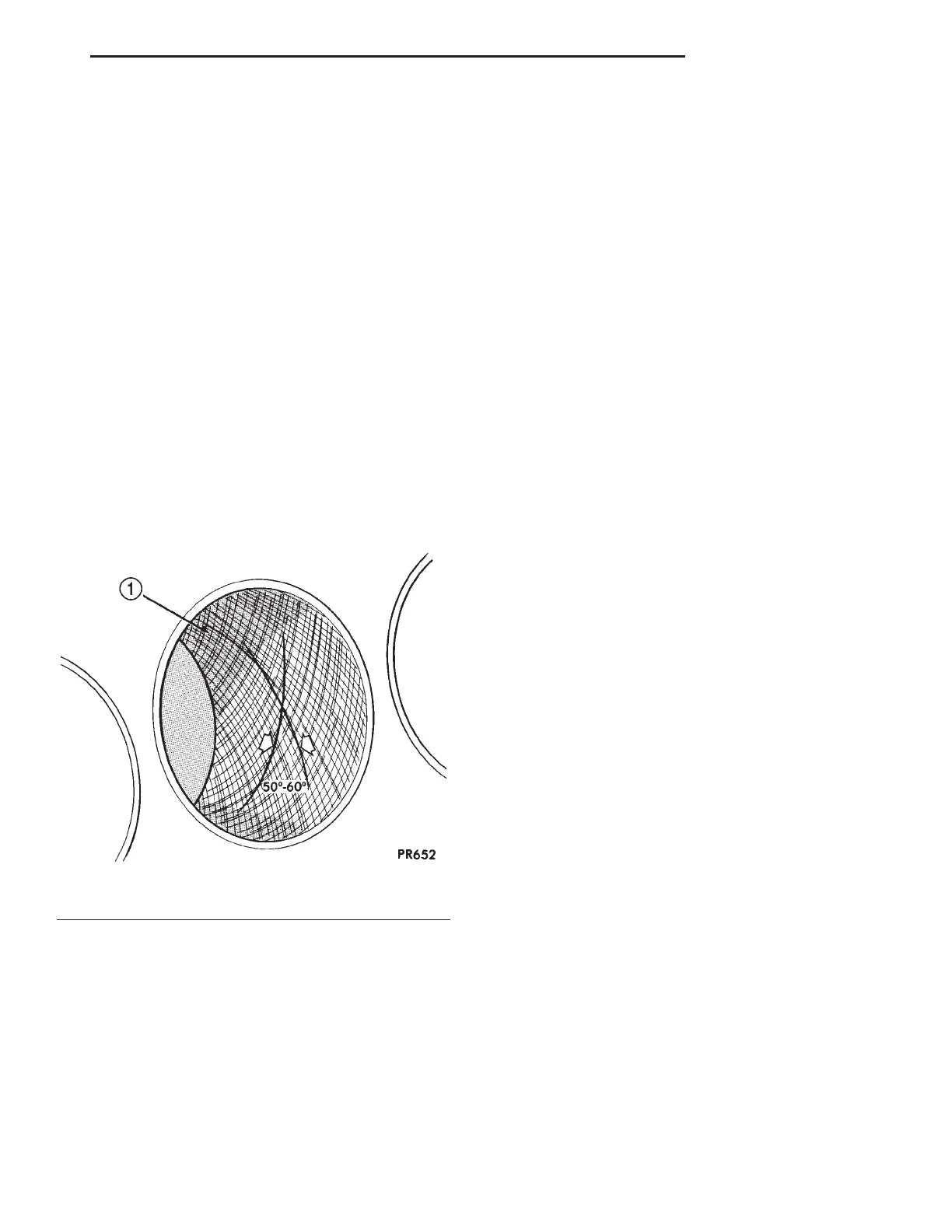
(3) Honing should be done by moving the hone up
and down fast enough to get a cross-hatch pattern.
When hone marks intersect at 50-60 degrees, the
cross hatch angle is most satisfactory for proper seat-
ing of rings (Fig. 18).
(4) A controlled hone motor speed between
200–300 RPM is necessary to obtain the proper cross-
hatch angle. The number of up and down strokes per
minute can be regulated to get the desired 50–60
degree angle. Faster up and down strokes increase
the cross-hatch angle.
(5) After honing, it is necessary that the block be
cleaned again to remove all traces of abrasive.
CAUTION: Ensure all abrasives are removed from
engine parts after honing. It is recommended that a
solution of soap and hot water be used with a
brush and the parts then thoroughly dried. The bore
can be considered clean when it can be wiped
clean with a white cloth and cloth remains clean.
Oil the bores after cleaning to prevent rusting.
HYDROSTATIC LOCKED ENGINE
When an engine is suspected to be hydrostatically
locked, regardless of what caused the problem, the
following steps should be used.
CAUTION: DO NOT use starter motor to rotate the
engine, severe damage may occur.
(1) Inspect air cleaner, induction system and
intake manifold to insure system is dry and clear of
foreign material.
(2) Remove negative battery cable.
(3) Place a shop towel around the spark plugs
when removing them from the engine. This will catch
any fluid that may possibly be in the cylinder under
pressure.
(4) With all spark plugs removed, rotate engine
crankshaft using a breaker bar and socket.
(5) Identify the fluid in the cylinder(s) (i.e., cool-
ant, fuel, oil or other).
(6) Make sure all fluid has been removed from the
cylinders. Inspect engine for damage (i.e., connecting
rods, pistons, valves, etc.).
(7) Repair engine or components as necessary to
prevent this problem from re-occurring.
CAUTION: Squirt approximately one teaspoon of oil
into the cylinders, rotate engine to lubricate the cyl-
inder walls to prevent damage on restart.
(8) Install new spark plugs.
(9) Drain engine oil and remove oil filter.
(10) Fill engine with specified amount of approved
oil and install new oil filter.
(11) Connect negative battery cable.
(12) Start engine and check for any leaks.
PISTONS
The pistons have been cast and machined to one
size and weight. The piston and rod assemblies are
matched to weigh the same for engine balance.
FITTING PISTONS
Piston and cylinder wall must be clean and dry.
Piston diameter should be measured 90 degrees to
piston pin at size location shown in (Fig. 19). Cylin-
der bores should be measured halfway down the cyl-
inder bore and transverse to the engine crankshaft
center line. Refer to Engine Specifications. Pistons
and cylinder bores should be measured at nor-
mal room temperature, 70°F (21°C).
Fig. 18 Cylinder Bore Cross-Hatch Pattern
1 – CROSS-HATCH PATTERN
LH 2.7L ENGINE 9 - 23
SERVICE PROCEDURES (Continued)