(3) Install three gearbox screws and one tie down
bracket screw, if applicable. Tighten to 5.6 to 8 N·m
(50 to 70 in. lbs.) torque.
(4) Install regulator, using the switch, test opera-
tion of motor.
WINDOW SWITCHES
MASTER SWITCH
REMOVAL
INTREPID AND CONCORDE
(1) Open hood and disconnect the negative battery
cable remote terminal from the remote battery post
(Fig. 4).
(2) Remove driver’s door trim panel. Refer to
Group 23-Body, Front Door Trim Removal and Instal-
lation.
(3) Remove three mounting screws.
(4) Remove switch and disconnect wire connector.
LHS and 300M
(5) Open hood and disconnect the negative battery
cable remote terminal from the remote battery post
(Fig. 4).
(6) Using a trim stick (special tool #C-4755) or
equivalent, gently pry up on switch trim bezel and
lift up and out of trim panel.
(7) Disconnect wire connector from rear of switch
and remove switch from vehicle.
INSTALLATION
For installation, reverse the above procedures.
PASSENGER SWITCH
REMOVAL
(1) Open hood and disconnect the negative battery
cable remote terminal from the remote battery post
(Fig. 4).
(2) Remove passenger door trim panel. Refer to
Group 23-Body, Front Door Trim Removal and Instal-
lation.
(3) Disconnect switch wire connector.
(4) Remove switch from bezel and vehicle.
INSTALLATION
For installation, reverse the above procedures.
REAR DOOR SWITCHES
REMOVAL
(1) Open hood and disconnect the negative battery
cable remote terminal from the remote battery post
(Fig. 4).
(2) Open rear door.
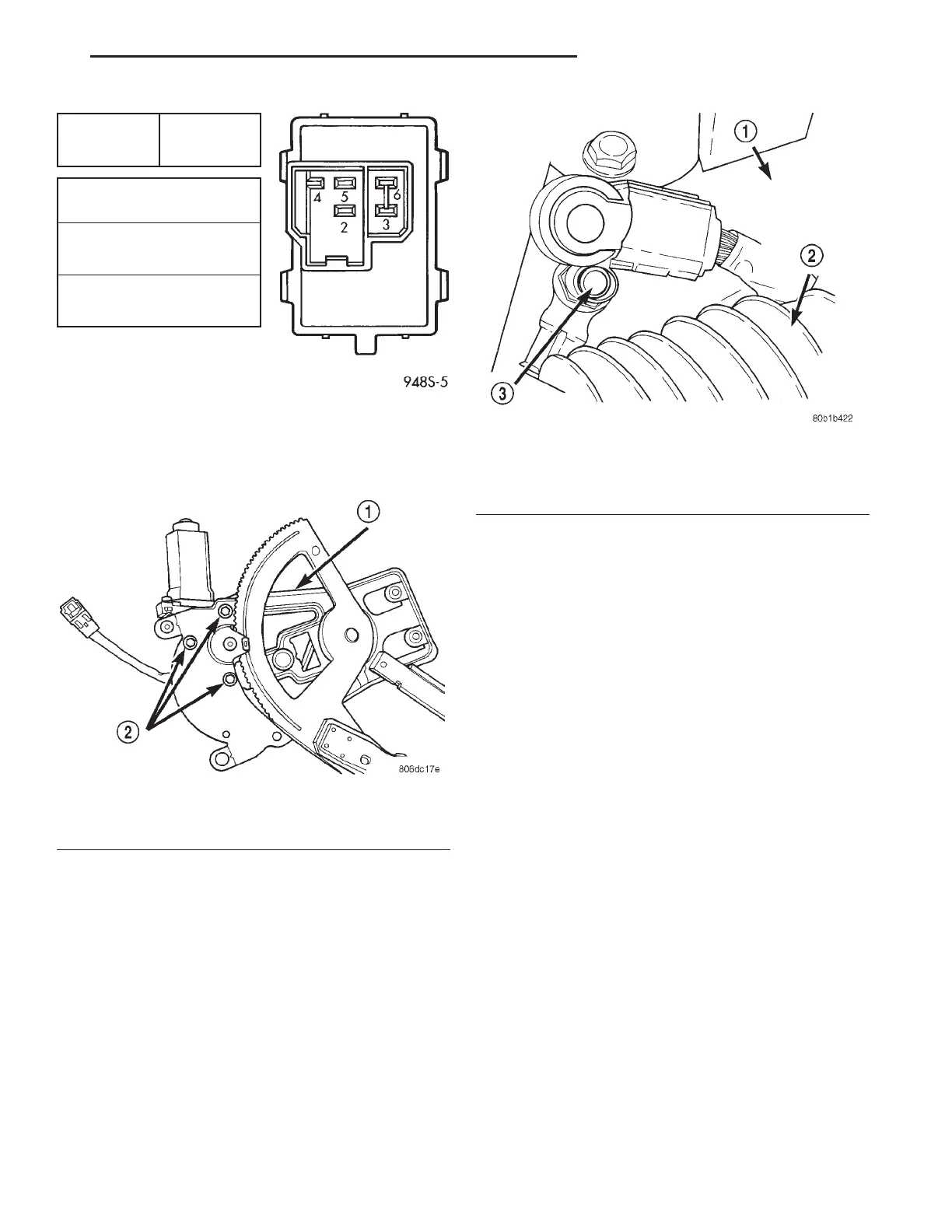
SWITCH
POSITION
CONTINUITY
BETWEEN
TERMINALS
OFF8 PIN2to5
PIN6to3
UP PIN6to3
PIN4to5
DOWN PIN 2 to 5
PIN4to3
Fig. 2 Passenger Window Switch
Fig. 3 Motor Removal
1 – CLAMP REGULATOR TO SECTOR GEAR
2 – MOTOR MOUNTING SCREWS
Fig. 4 Negative Battery Cable Remote Terminal
1 – RIGHT STRUT TOWER
2 – AIR CLEANER INLET TUBE
3 – REMOTE TERMINAL
LH POWER WINDOW SYSTEMS 8S - 3
REMOVAL AND INSTALLATION (Continued)