INSTALL
(1) Install steering knuckle on ball joint stud.
Install steering knuckle to lower ball joint attaching
bolt and nut into steering knuckle (Fig. 23). Tighten
the attaching bolt to a torque of 55 N·m (40 ft. lbs.).
(2) Position steering knuckle into strut assembly.
CAUTION: The strut assembly to steering knuckle
bolts are serrated were they go through strut
assembly and steering knuckle. When installing
bolts, turn nuts onto bolts DO NOT TURN BOLTS IN
STEERING KNUCKLE. If bolts are turned damage to
steering knuckle will result.
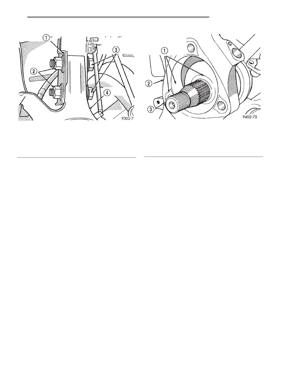
(3) Install the strut assembly to steering knuckle
attaching bolts (Fig. 25). Install nuts on attaching
bolts (Fig. 25). Tighten the strut clevis to steering
knuckle attaching bolt nuts to a torque of 203 N·m
(150 ft. lbs.).
CAUTION: Hub and bearing assembly mounting
surfaces on steering knuckle and halfshaft (Fig. 26)
must be smooth and completely free of foreign
material or nicks.
CAUTION: When installing hub and bearing assem-
bly into steering knuckle, be careful not to damage
the flinger disc (Fig. 20) on hub and bearing assem-
bly. If flinger disc becomes damaged, hub and bear-
ing assembly MUST not be used and MUST be
replaced with a new hub and bearing assembly.
(4) Install hub and bearing assembly onto stub
shaft and into steering knuckle until squarely seated
on face of steering knuckle.
(5) Install the 3 steering knuckle to hub and bear-
ing assembly attaching bolts (Fig. 19). Equally
tighten all 3 mounting bolts until hub and bearing
assembly is squarely seated against front of steering
knuckle. Then tighten all 3 hub and bearing assem-
bly mounting bolts to a torque of 110 N·m (80 ft. lbs.)
CAUTION: The hub and bearing assembly to stub
shaft retaining nut (Fig. 18) is a prevailing torque
nut and can not be reused. A NEW retaining nut
MUST be used when assembled.
(6) Install a NEW hub and bearing assembly to
stub shaft retaining nut (Fig. 18). Tighten, but do
not torque the hub nut at this time.
(7) Coat speed sensor head with High Temperature
Multipurpose E. P. Grease before installing into the
steering knuckle. Install speed sensor head into
steering knuckle. Install screw and tighten to a
torque of 7 N·m (60 in. lbs.)
(8) Install the braking disk back on the hub and
bearing assembly (Fig. 16).
(9) Install front brake caliper on steering knuckle.
Refer to Front Disc Brake Service in the Brake Sec-
tion of this service manual for caliper installation
procedure. Install the caliper to steering knuckle
attaching bolts (Fig. 15) and tighten them to a torque
of 19 N·m (168 in. lbs.).
(10) Install wheel and tire assembly on vehicle.
Tighten the wheel mounting stud nuts in proper
sequence until all nuts are torqued to half specifica-
Fig. 25 Strut To Steering Knuckle Attaching Bolts
1 – STRUT ASSEMBLY
2 – NUTS
3 – STRUT ASSEMBLY TO STEERING KNUCKLE ATTACHING
BOLTS
4 – STEERING KNUCKLE
Fig. 26 Hub And Bearing Assembly Mounting
Surfaces
1 – BE SURE THESE SURFACES ARE CLEAN AND FREE OF
KNICKS BEFORE INSTALLING BEARINGS
2 – STEERING KNUCKLE
3 – STUB AXLE
LH SUSPENSION 2 - 21
REMOVAL AND INSTALLATION (Continued)