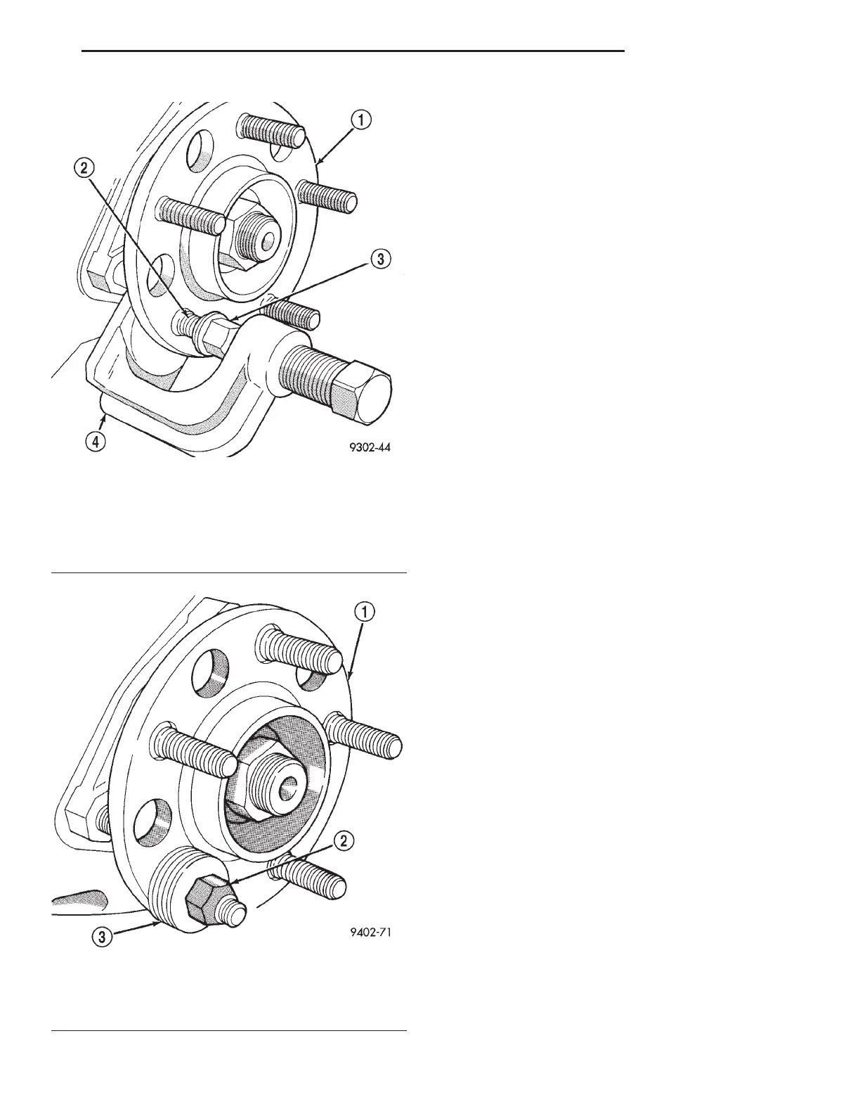
(2) Tighten the wheel lug nut, pulling the wheel
stud into the flange of the hub and bearing assembly.
When the head of the stud is fully seated against the
bearing flange, remove lug nut and washers from
wheel stud.
(3) Install the rotor on the hub and bearing assem-
bly (Fig. 59).
(4) Install front brake caliper back over braking
disc and align with caliper mounting holes on steer-
ing knuckle. Refer to Disc Brake Caliper in the
Removal And Installation Section in the Brake Group
of this service manual for the caliper installation pro-
cedure. Install the caliper to steering knuckle guide
pin bolts (Fig. 58) and tighten to a torque of 19 N·m
(168 in. lbs.).
(5) Install wheel and tire assembly on vehicle.
Tighten the wheel mounting stud nuts in proper
sequence until all nuts are torqued to half specifica-
tion. Then repeat the tightening sequence to the full
specified torque of 129 N·m (95 ft. lbs.).
(6) Lower the vehicle to the ground.
DISASSEMBLY AND ASSEMBLY
STRUT ASSEMBLY (FRONT)
The Strut assembly must be removed from the
vehicle for it to be disassembled and assembled.
Refer to REMOVAL AND INSTALLATION in this
section for the required procedure.
For the disassembly and assembly of the strut
assembly, use strut spring compressor, Pentastar Ser-
vice Equipment (PSE) tool W-7200, or the equivalent,
to compress the coil spring. Follow the manufactur-
er’s instructions closely.
DISASSEMBLY
(1) If both struts are being serviced at the same
time, mark the coil spring and strut assembly accord-
ing to which side of the vehicle the strut was
removed from, and which strut the coil spring was
removed from.
(2) Position the strut assembly in the strut coil
spring compressor following the manufacturers
instructions (Fig. 62). The strut clevis bracket should
be positioned outward. It will be necessary to turn
the strut assembly so the steering arm will clear the
compressor arm. Position the upper and lower hooks
on the coil spring, then place a clamp on the lower
end of the coil spring, so the strut is held in place
once the strut shaft nut is removed (Fig. 62).
Fig. 60 Removing Wheel Stud From Hub And
Bearing
1 – HUB/BEARING ASSEMBLY
2 – WHEEL STUD
3 – LUG NUT
4 – SPECIAL TOOL C-4150
Fig. 61 Installing Wheel Stud Into Hub And Bearing
1 – HUB/BEARING ASSEMBLY
2 – WHEEL LUG NUT
3 – WASHERS
LH SUSPENSION 2 - 33
REMOVAL AND INSTALLATION (Continued)