(17) Re-tape the wire harness starting 1-1/2 inches
behind the connector and 2 inches past the repair.
(18) Connect battery, and test all affected systems.
DIODE REPLACEMENT
(1) Disconnect the battery.
(2) Locate the diode in the harness, and remove
the protective covering.
(3) Remove the diode from the harness, pay atten-
tion to the current flow direction (Fig. 19).
(4) Remove the insulation from the wires in the
harness. Only remove enough insulation to solder in
the new diode.
(5) Install the new diode in the harness, making
sure current flow is correct. If necessary refer to the
appropriate wiring diagram for current flow.
(6) Solder the connection together using rosin core
type solder only. Do not use acid core solder.
(7) Tape the diode to the harness using electrical
tape making, sure the diode is completely sealed
from the elements.
(8) Re-connect the battery, and test affected sys-
tems.
SPECIAL TOOLS
WIRING/TERMINAL
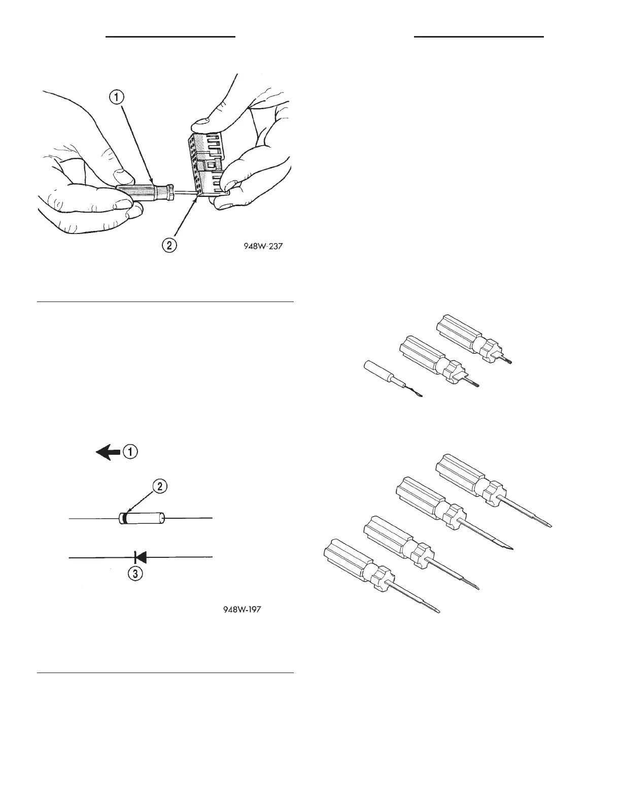
Fig. 18 Terminal Removal Using Special Tool
1 – FROM SPECIAL TOOL KIT 6680
2 – CONNECTOR
Fig. 19 Diode Identification
1 – CURRENT FLOW
2 – BAND AROUND DIODE INDICATES CURRENT FLOW
3 – DIODE AS SHOWN IN THE DIAGRAMS
Probing Tool Package 6807
Terminal Pick 6680
8W - 01 - 14 8W - 01 GENERAL INFORMATION LH
SERVICE PROCEDURES (Continued)