OPERATION
The PCM operates the Automatic Shut Down
(ASD) relay and fuel pump relay through one ground
path. The PCM operates them by switching the
ground path for the relays on and off. Both relays
turn on and off at the same time.
The ASD relay connects battery voltage to the fuel
injectors and ignition coil. The fuel pump relay con-
nects battery voltage to the fuel pump.
The PCM turns the ground path off when the igni-
tion switch is in the Off position. Both relays are off.
When the ignition switch is in the On or Crank posi-
tion, the PCM monitors the crankshaft position sen-
sor and camshaft position sensor signals to
determine engine speed. If the PCM does not receive
a crankshaft position sensor signal and camshaft
position sensor signal when the ignition switch is in
the Run position, it de-energizes both relays. When
the relays are de-energized, battery voltage is not
supplied to the fuel injectors, ignition coil and fuel
pump.
PROPORTIONAL PURGE SOLENOID—PCM
OUTPUT
DESCRIPTION
All vehicles use a proportional purge solenoid. The
solenoid regulates the rate of vapor flow from the
EVAP canister to the throttle body. The PCM oper-
ates the solenoid.
OPERATION
During the cold start warm-up period and the hot
start time delay, the PCM does not energize the sole-
noid. When de-energized, no vapors are purged.
The proportional purge solenoid operates at a fre-
quency of 200 hz and is controlled by an engine con-
troller circuit that senses the current being applied
to the proportional purge solenoid (Fig. 11) and then
adjusts that current to achieve the desired purge
flow. The proportional purge solenoid controls the
purge rate of fuel vapors from the vapor canister and
fuel tank to the engine intake manifold.
EXHAUST GAS RECIRCULATION (LSEGR)
DESCRIPTION
The EGR valve consists of three major components.
First there is the pintle, valve seat, and housing
which contains and regulates the gas flow. Second
there is the armature, return spring, and solenoid
coil to provide the operating force to regulate the
flow by changing the pintle position. The solenoid coil
assembly is in parallel with a diode and connects to
the two connectors in the connector assembly. The
third major component which senses pintle position
and is connected to the three connectors in the elec-
trical connector.
OPERATION
The exhaust gas recirculation flow is determined
by the engine controller. For a given set of conditions,
the engine controller knows the ideal exhaust gas
recirculation flow to optimize NOx and fuel economy
as a function of the pintle position. Pintle position is
obtained from the position sensor. The engine con-
troller adjusts the duty cycle of 128 Hz power sup-
plied to the solenoid coil to obtain the correct
position.
MANIFOLD TUNING VALVE (MTV)—PCM
OUTPUT
DESCRIPTION
The valve opens a crossover passage in that con-
nects both sides of the intake manifold plenum (Fig.
12). It is an elecrtic motor.
OPERATION
The PCM controls the MTV solenoid. The manifold
tuning valve optimizes acoustical tuning of the
intake system during wide open throttle operation
throughout the RPM range.
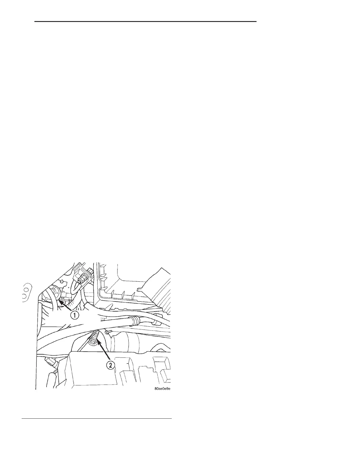
Fig. 11 Proportional Purge Solenoid
1 – PROPORTIONAL PURGE SOLENOID
2 – O2 SENSOR
LH FUEL SYSTEM 14 - 33
DESCRIPTION AND OPERATION (Continued)